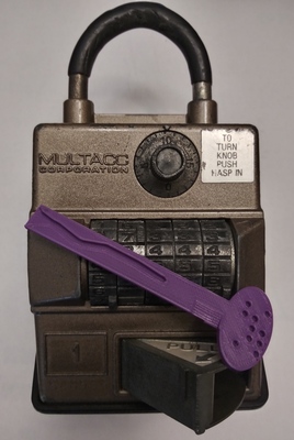
MULTACC Corporation was founded in the 1980s to produce a series of lockboxes created by inventor Derek J. Gable, which were designed to be more secure than the standard keybox by introducing two-factor authentication (opening only with a key and a corresponding code) and a self-contained audit trail designed to last for 35 years.1 The first of the PCR line of lockboxes (PCR being an acronym for programmable-combination-recording2) implemented these features entirely mechanically, with electronic versions coming later.
These lockboxes sold extremely well, at one time comprising 80% of keybox sales worldwide.1
More information and excellent analyses of the mechanical versions can be found in the links, including the patent, a video on operation by Will Phoneman and complete teardown by GWeins2001.
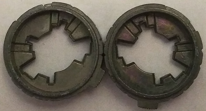
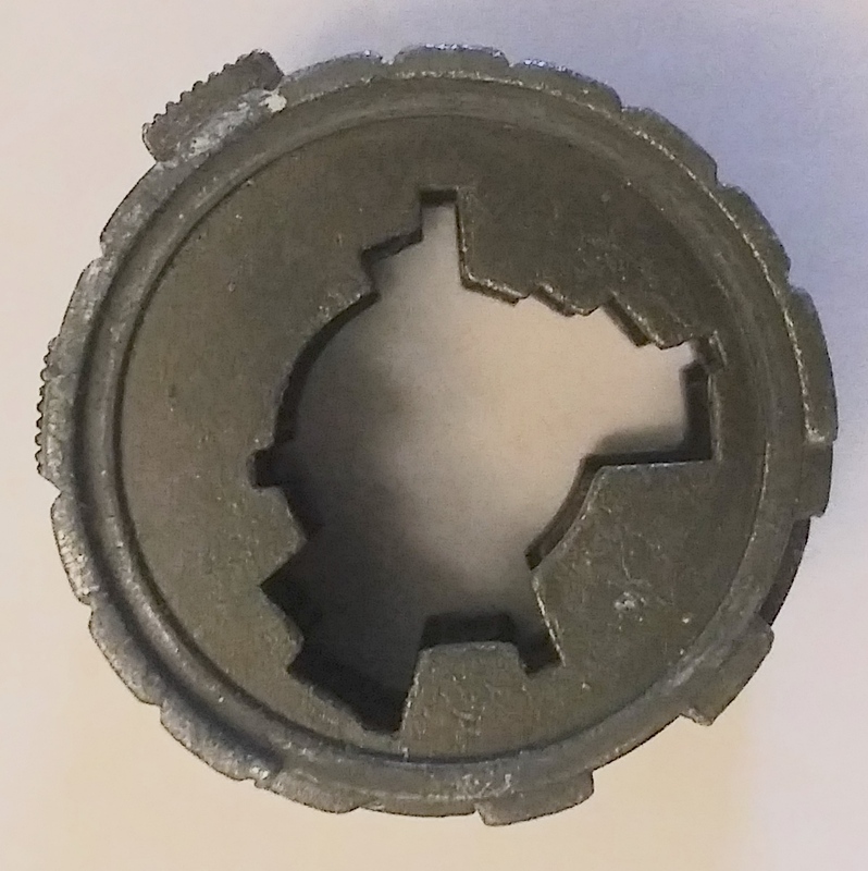
Exactly five different code wheels were manufactured1, mysteriously labeled B, E, F, G, H. They all have false gates on the bottom and top sides, as well as serrations on the tips that match serrations made in the sliders, which prevent a close but inexact match being forced through.
Wheels E&F and G&H are mirror images of each other, including false gate positions.
By mirror images, we mean that E1 + F7 = 8 = E2 + F6 = E3 + F5 = …
(The symmetry turns out to be coincidence, not a way for manufacturing to reuse parts,
as each wheel still needs its own tooling.1)
There never was a wheel A!
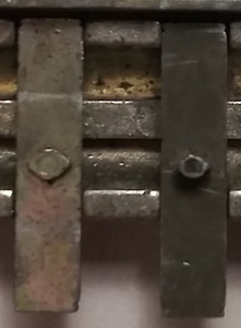
The pegs on the sliders that interact with the key come in at least two different variations, with unique diameters and nub heights, requiring distinct bitting depth and track depth data for each. This was an intentional design choice1 to further frustrate would-be attackers. These variations in slider pegs require track-in-track keys2 and are difficult to overcome with improvised tools.
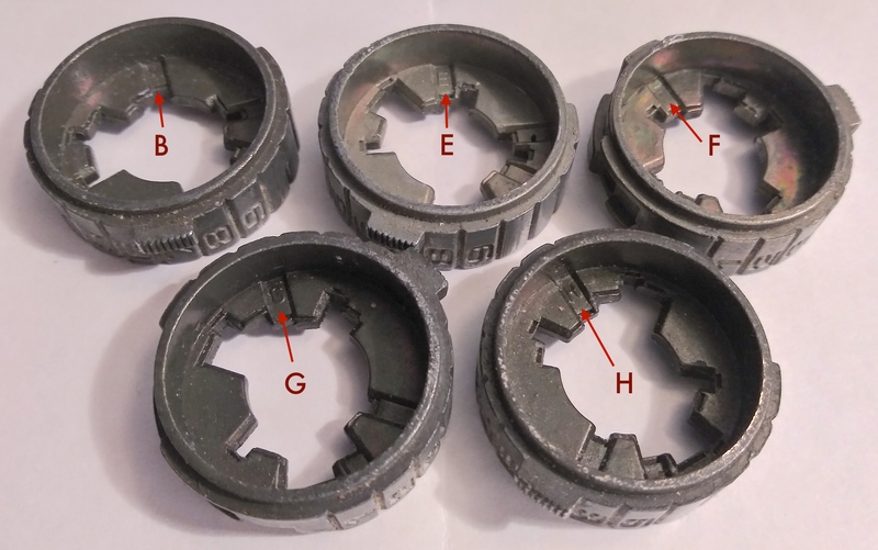
If the box is held upright, maximum lift is 1, minimum lift is 7, using GWeins2001's terminology on Keypicking.
1 | 2 | 3 | 4 | 5 | 6 | 7 | |
---|---|---|---|---|---|---|---|
B | 5 | 6 | 7 | 3 | 1 | 4 | 2 |
E | 4 | 6 | 7 | 1 | 2 | 5 | 3 |
F | 5 | 3 | 6 | 7 | 1 | 2 | 4 |
G | 3 | 5 | 1 | 2 | 4 | 7 | 6 |
H | 2 | 1 | 4 | 6 | 7 | 3 | 5 |
"Top" refers to false gates encountered when a slider is put at maximum lift, and "bottom" when a slider is at minimum lift.
Top | Bottom | |
---|---|---|
B | 1 | 4, 6 |
E | 2 | 5, 7 |
F | 1, 3 | 6 |
G | 5, 7 | 4 |
H | 4 | 1, 3 |
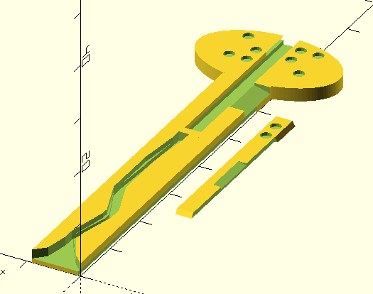
SgrA* created really nifty 3D-printed keys (video), but hasn't been able to distribute a CAD file for his models yet. I've attempted a re-creation of his work in an OpenSCAD format, allowing you to print arbitrary keys, which hopefully work and slide relatively smoothly in and out of the keyway.
When printing solid keys, I've found that setting at least 30% infill in the slicer greatly reduces the risk of key breakage.