The Supra Marc seems to be a clone of the form factor and multi-factor authentication of MULTACC PCR lockboxes,
while having a distinct internal locking mechanism (patent US4895036.)
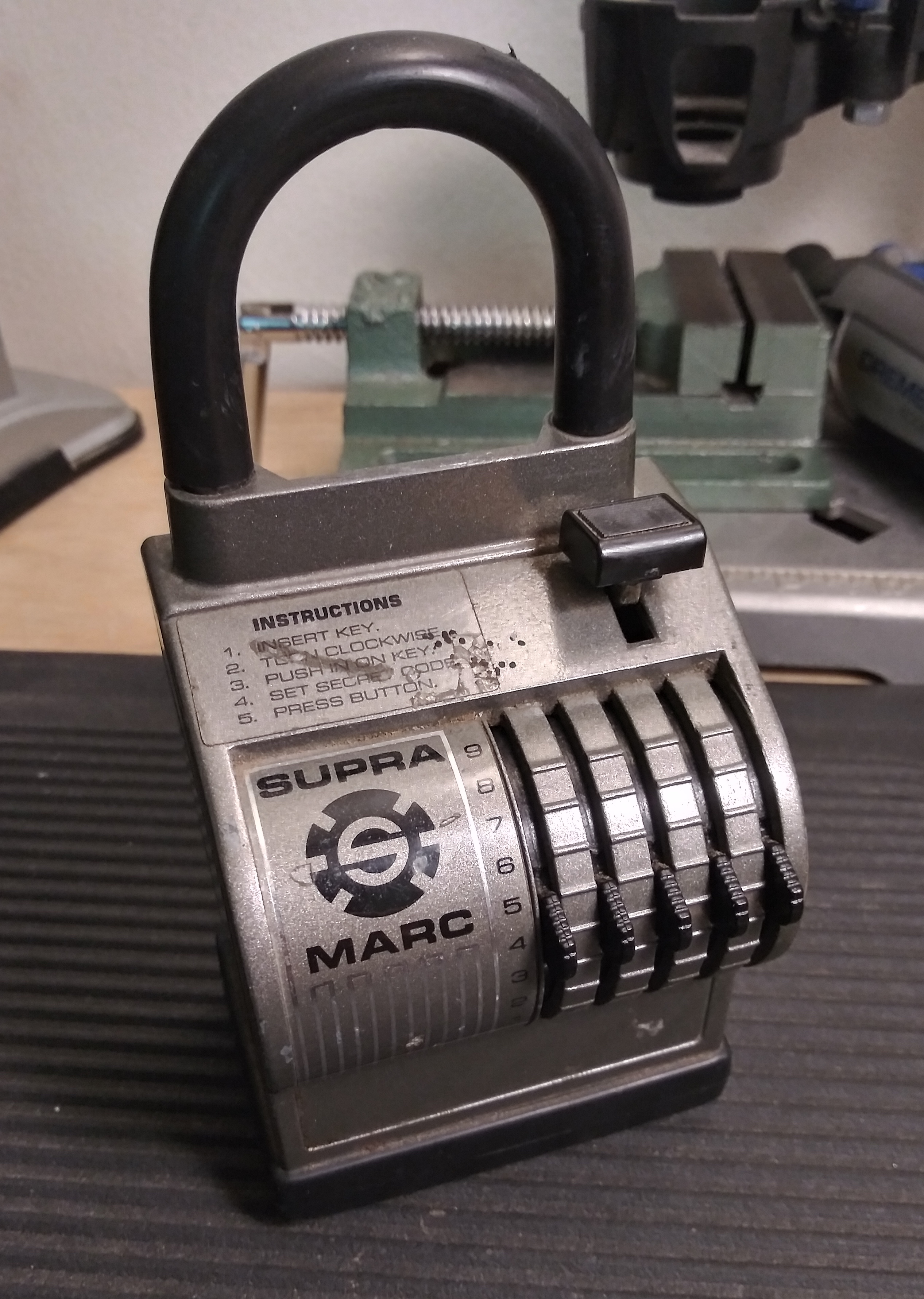
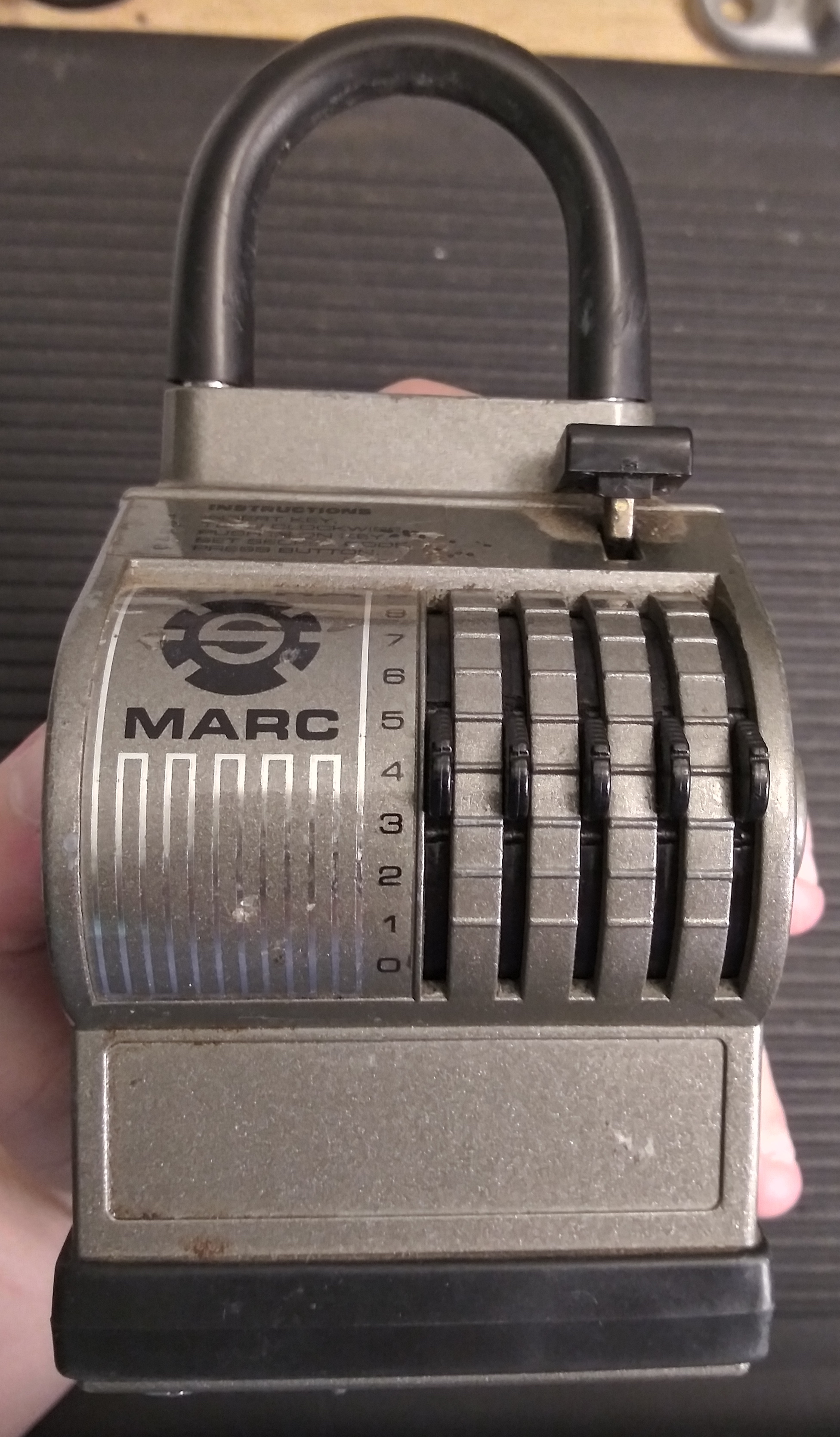
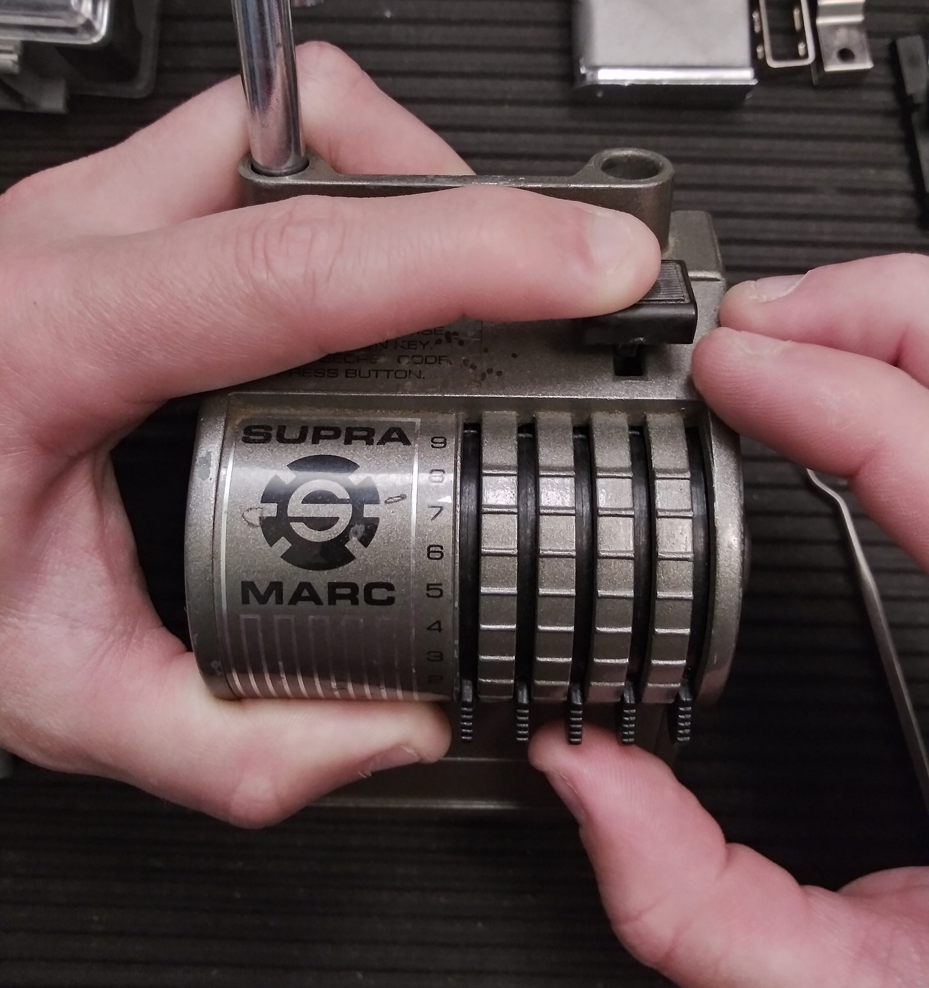
The keybox mechanism boils down to being a combination lock where each code wheel can be adjusted in increments theoretically
from 0-19; however, the tabs on the front of the lock can only move a wheel from 0-9 increments, and a key is needed to further
rotate the internal elements to reach the full 0-19 range.
This is accomplished by separating code wheels from the outer black plastic combination rings, connecting the two with ball bearing
detents of varying strengths that allow a key to rotate the code wheel directly without disturbing the combination ring's orientation.
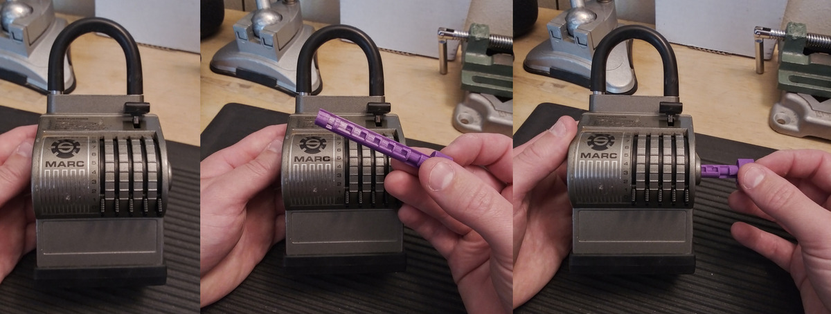
Practically, the key is inserted and turned first, rotating the code wheels before using the combination rings to rotate code wheels
further.
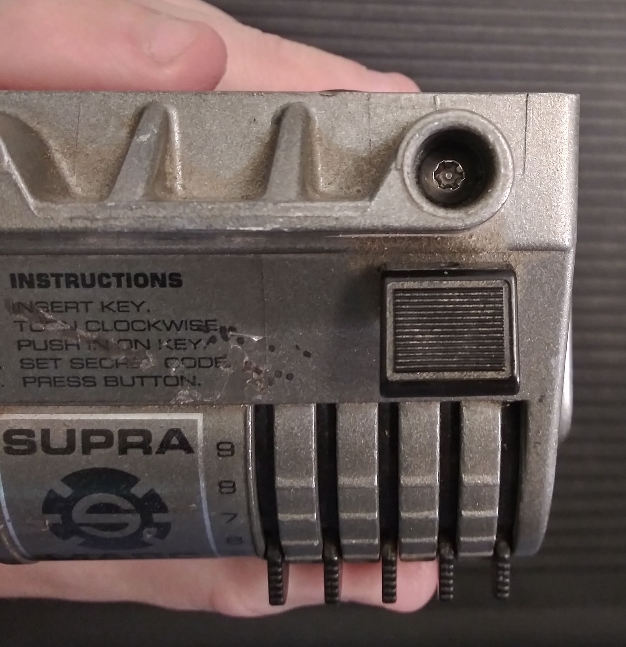
Operation
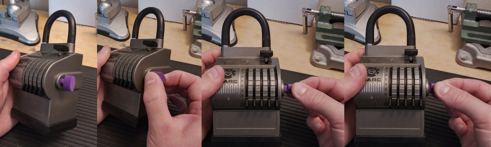
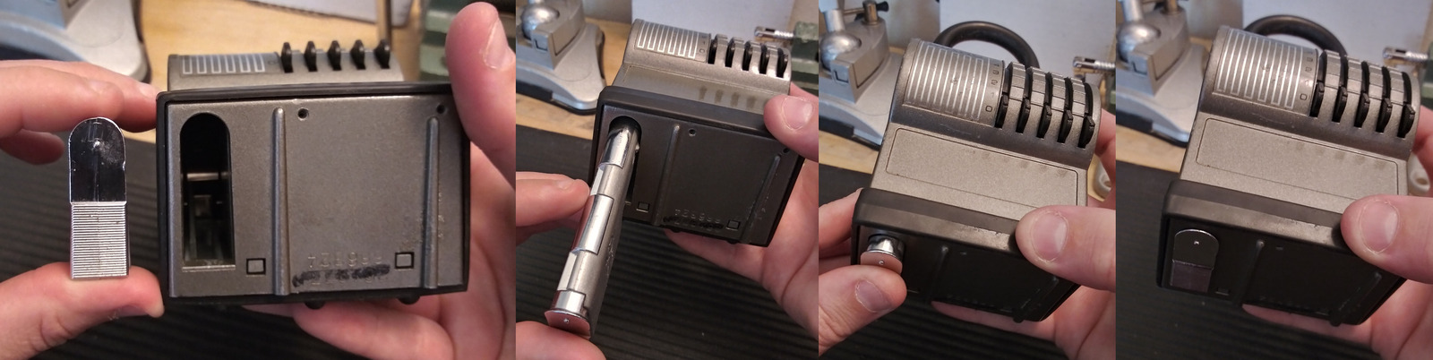
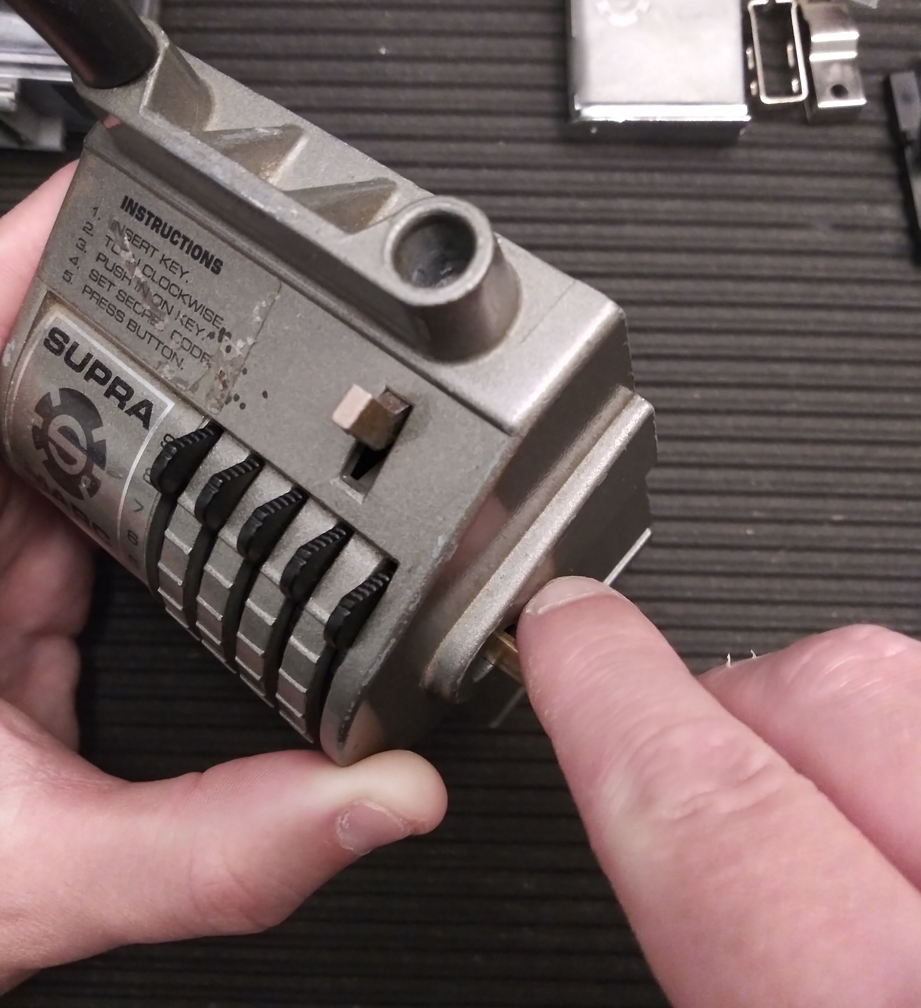
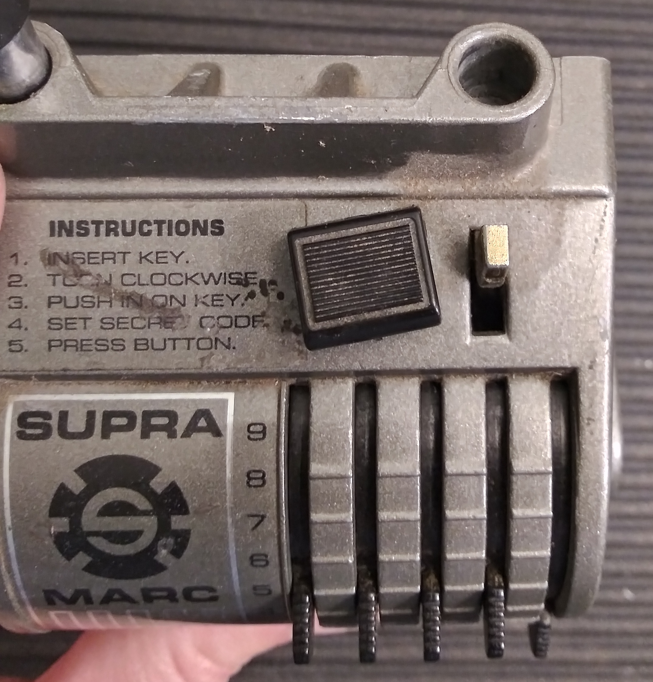
Set all tabs to 0 and insert the key.
Turn the key clockwise until it stops (you'll feel spring resistance in the last little bit of rotation.) Push the key inward
(you'll hear a snapping sound that's the key being recorded on the foil audit trail.)
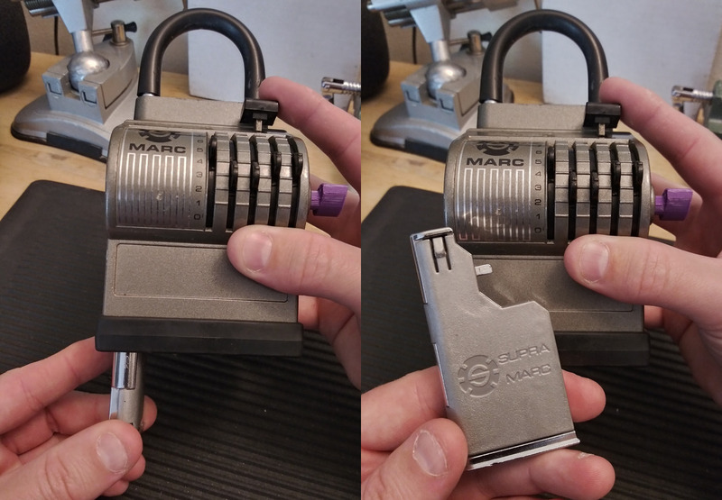
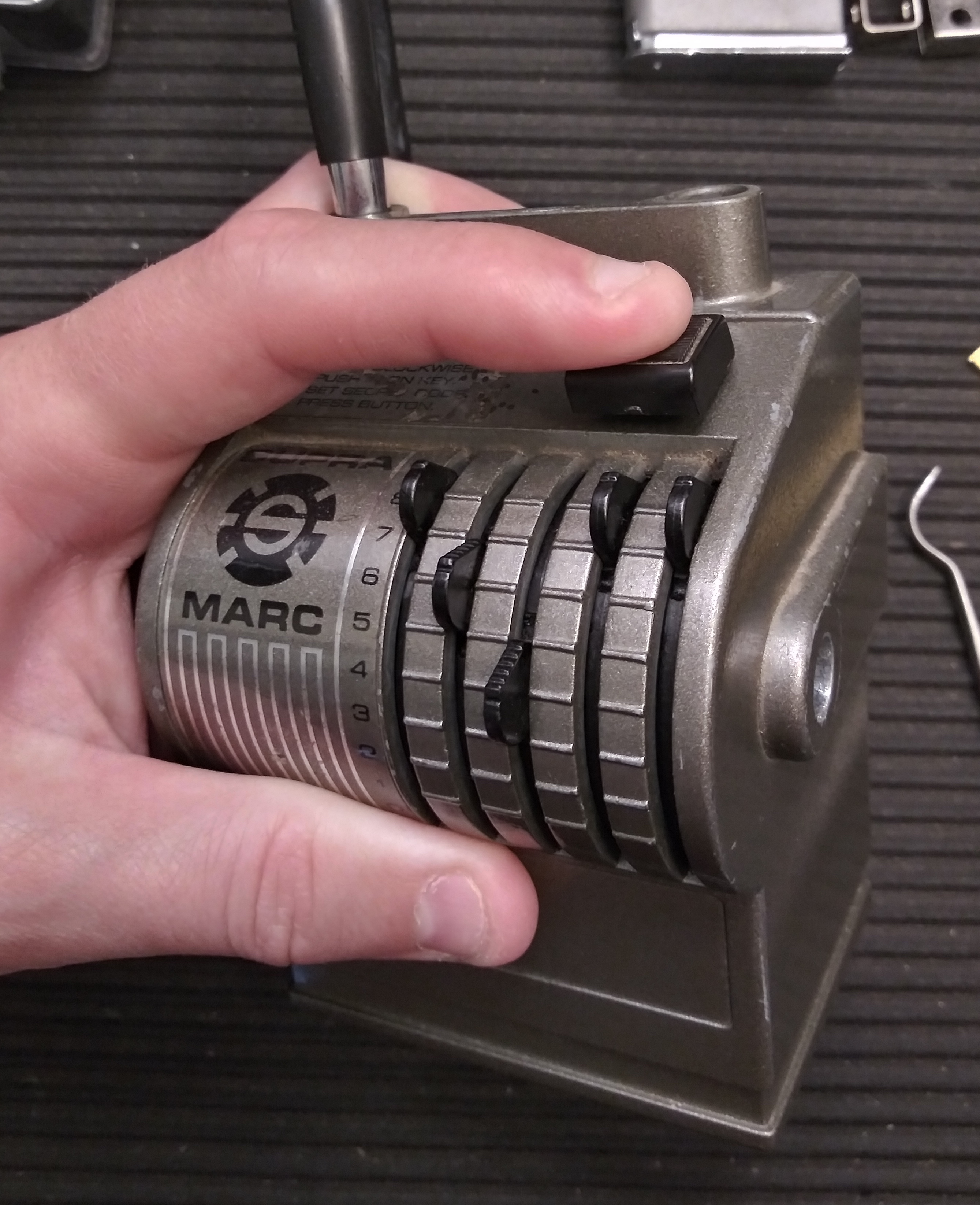
Leave the key in place and set the combination using the tabs on the front of the box. Once the combination is set, push the
actuator down and the keybox will drop partway out from the bottom left of the lockbox. Just pull the keybox further to fully remove.
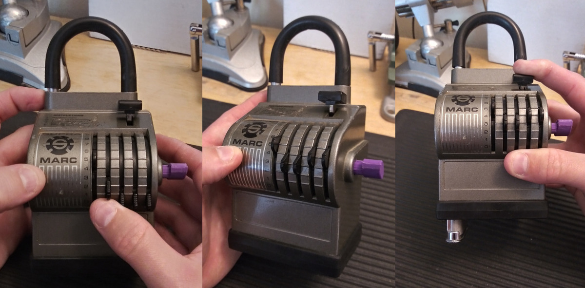
You can now turn the key counterclockwise all the way to a hard stop, where it can be withdrawn. Turning the key counterclockwise will
also return all the tabs to their 0 position.
To return the keybox, simply close it and push it upward to its resting position.
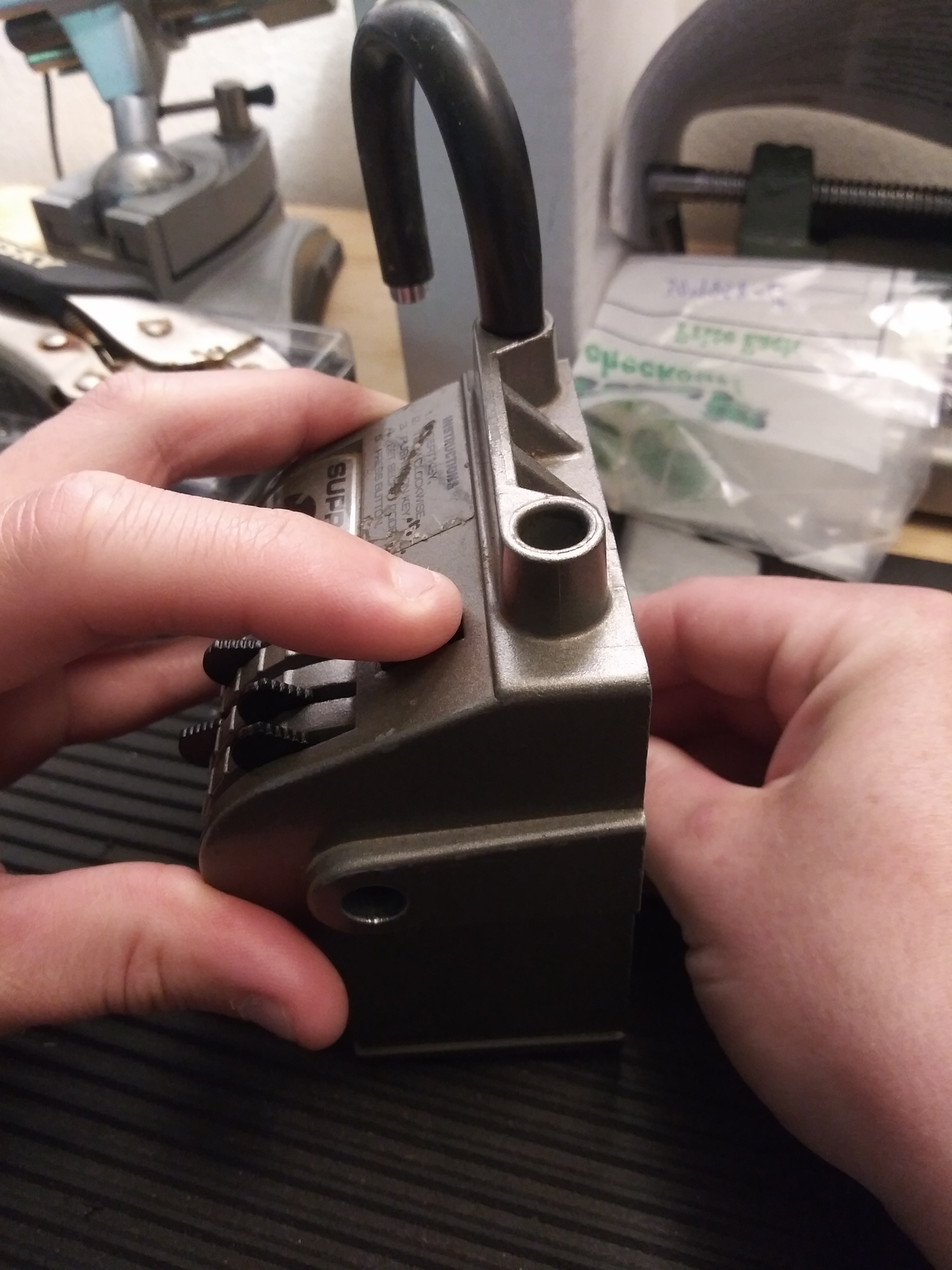
Disassembly
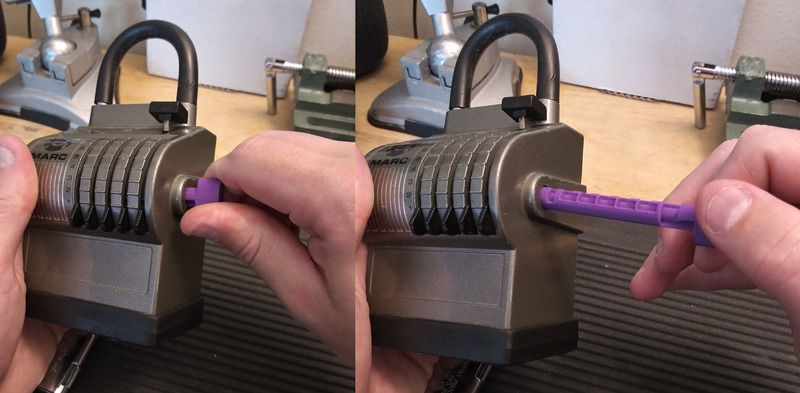
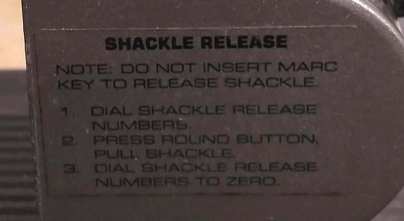
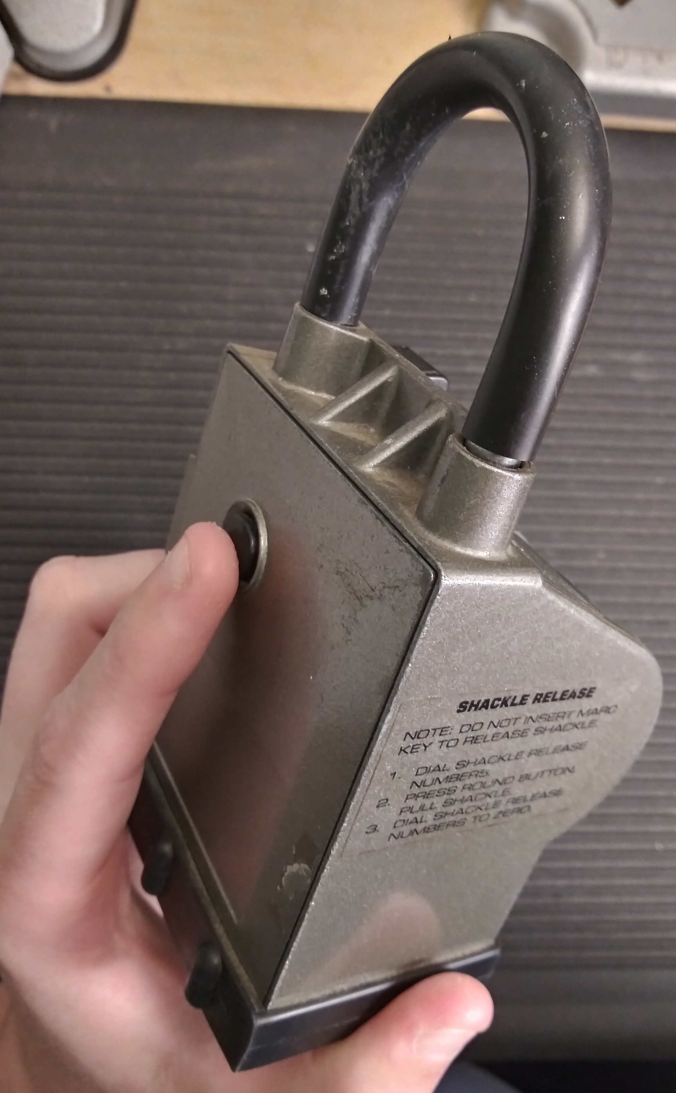
First we'll decode the shackle release code. This can be done by pressing in on the shackle release button and feeling for the
binding tab on the combination rings, then changing the number on the combination ring until it's no longer binding. Repeat
until all tabs are loose and the shackle release button depresses, freeing the shackle.
In my case, the shackle release code was 44444 (!)
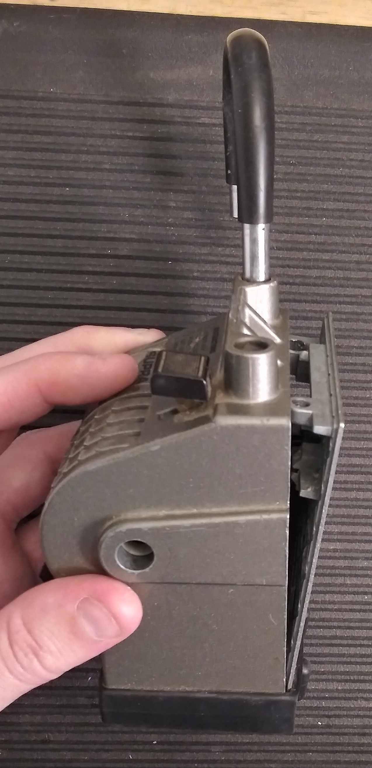
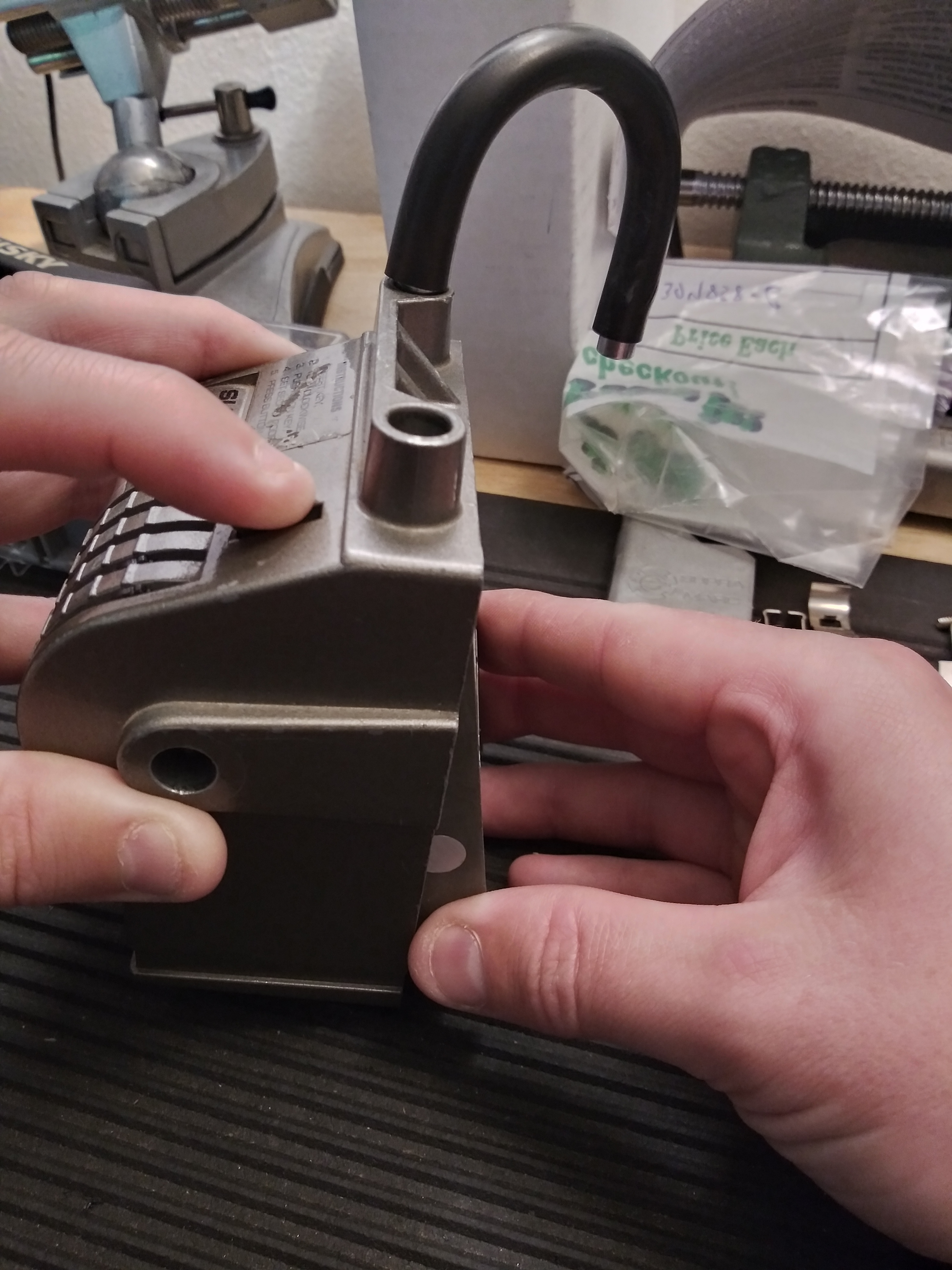
Remove the T15 Torx security screw in the right shackle hole.
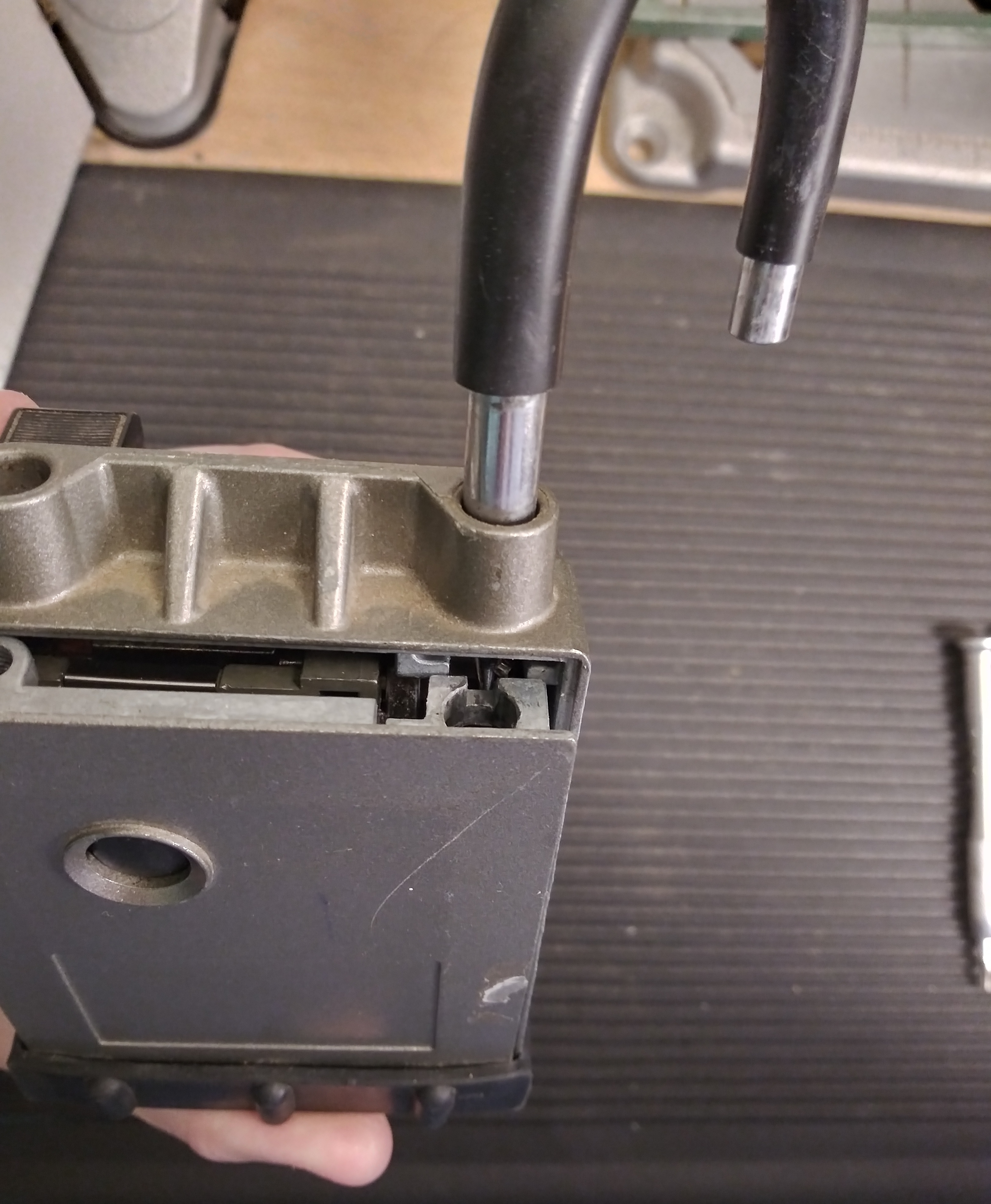
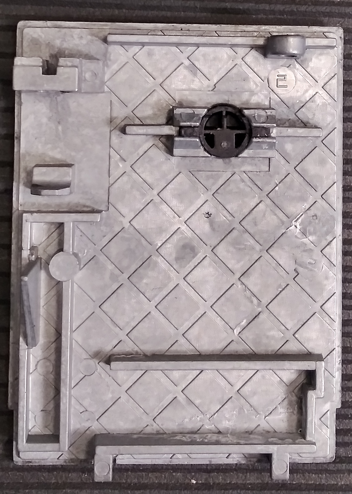
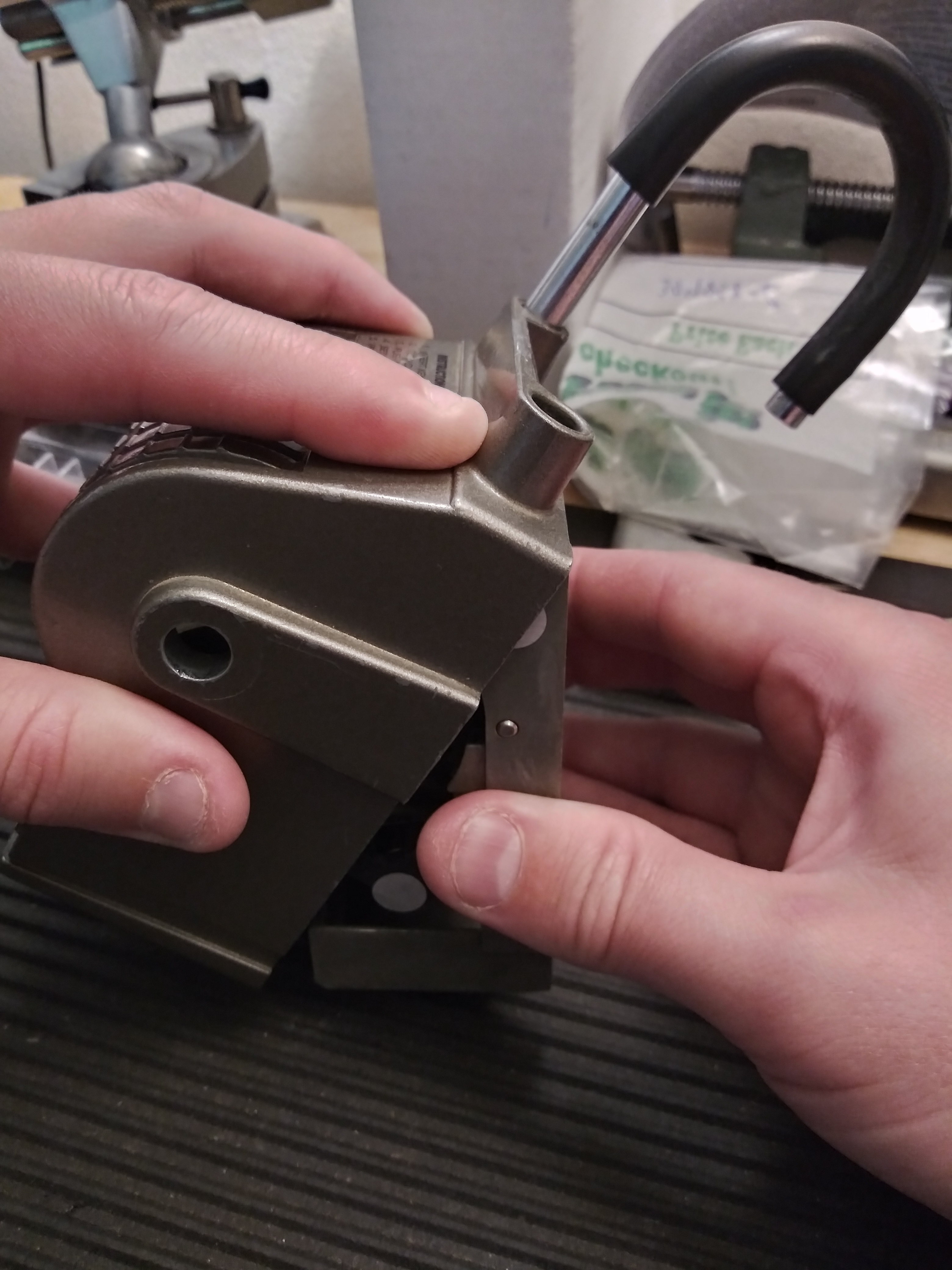
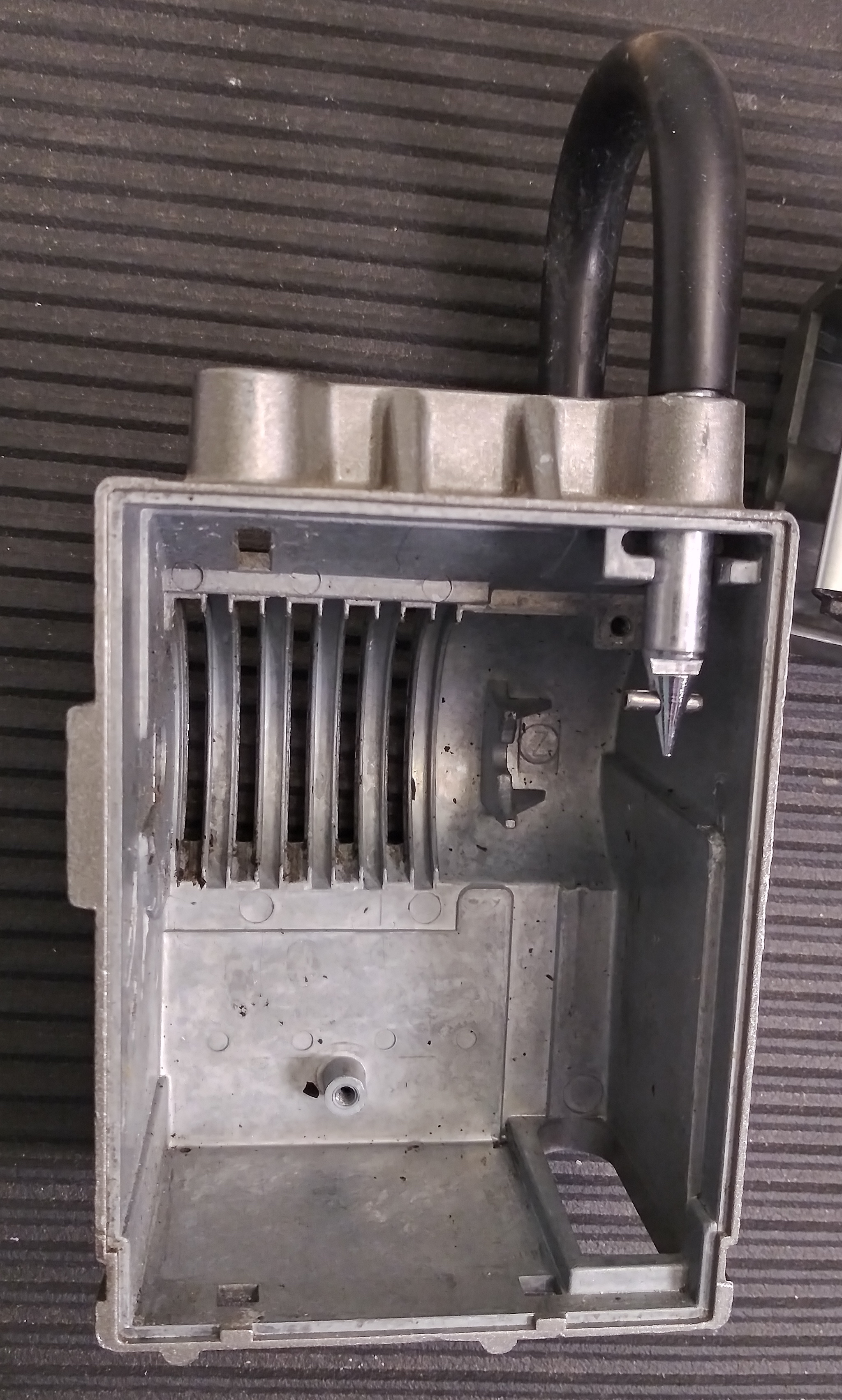
Gently pry the back cover outwards and upwards, pivoting from the bottom. Be careful because the interior tip of the shackle and
rubber boot will interfere; you can try to keep the shackle pulled all the way out and remove the rubber boot.
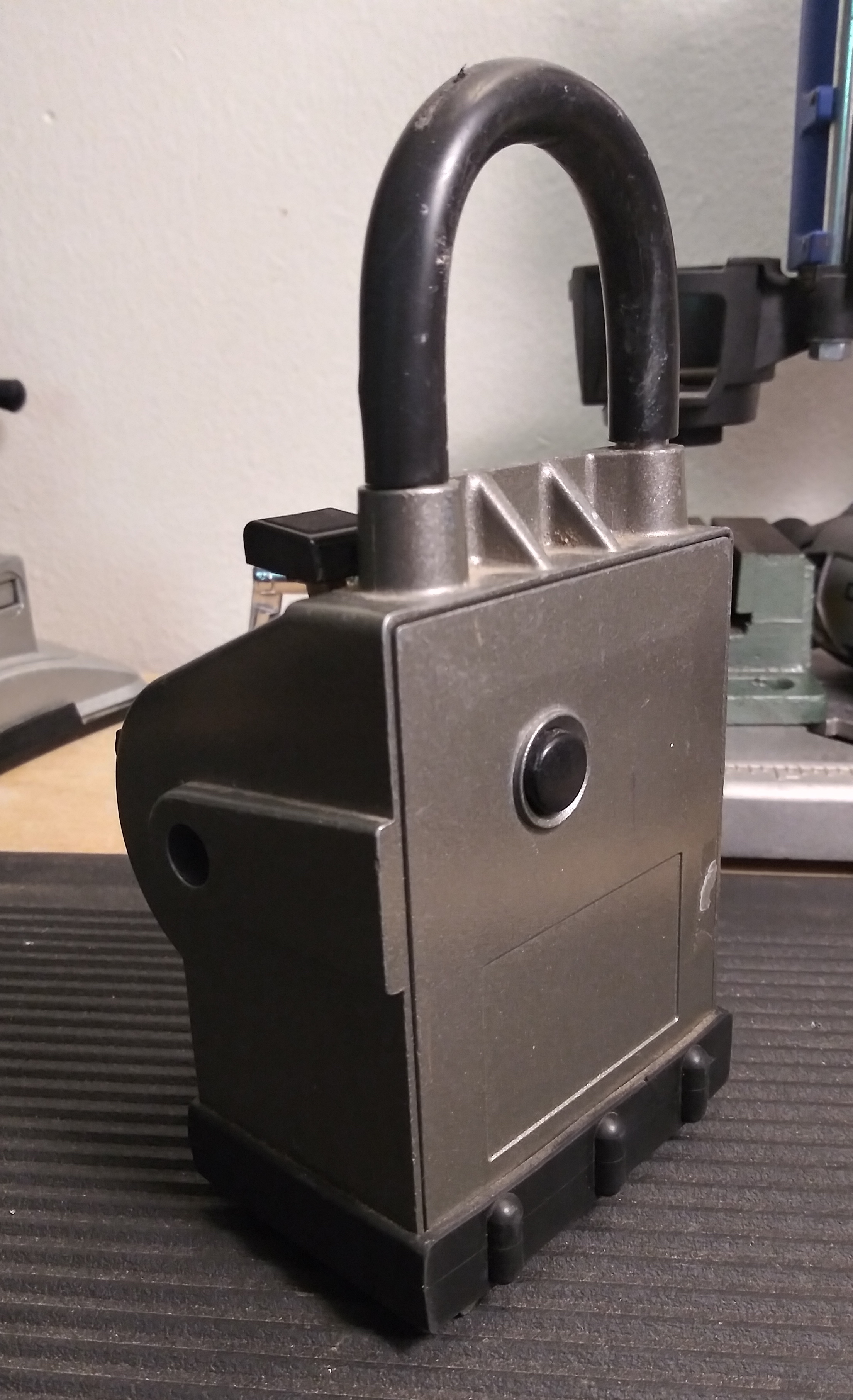
Back cover has nothing special going on besides the shackle release button.
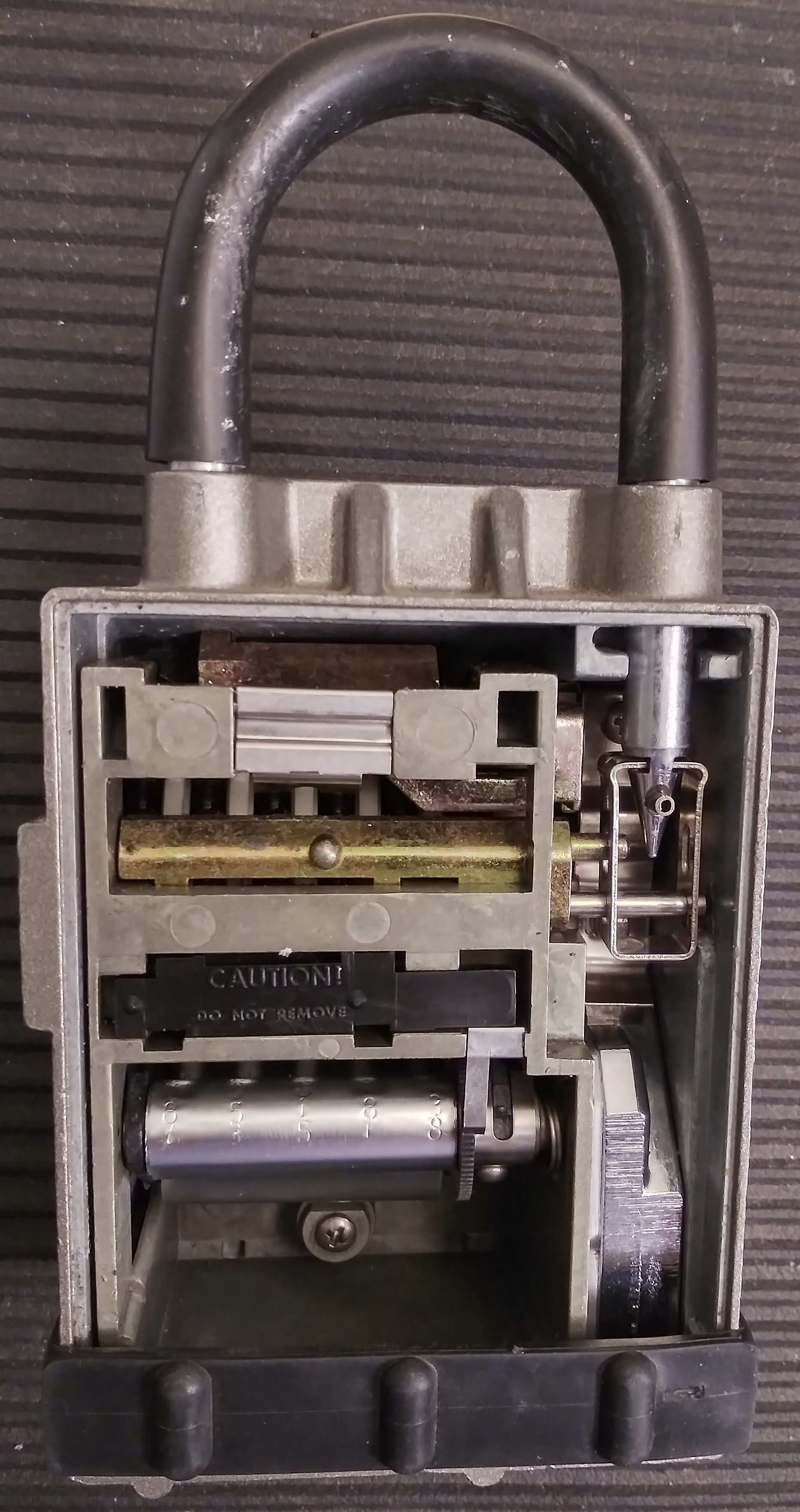
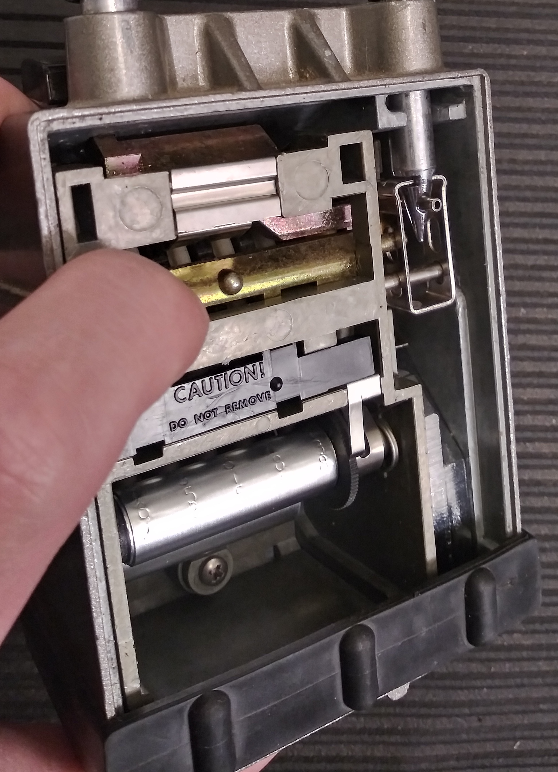
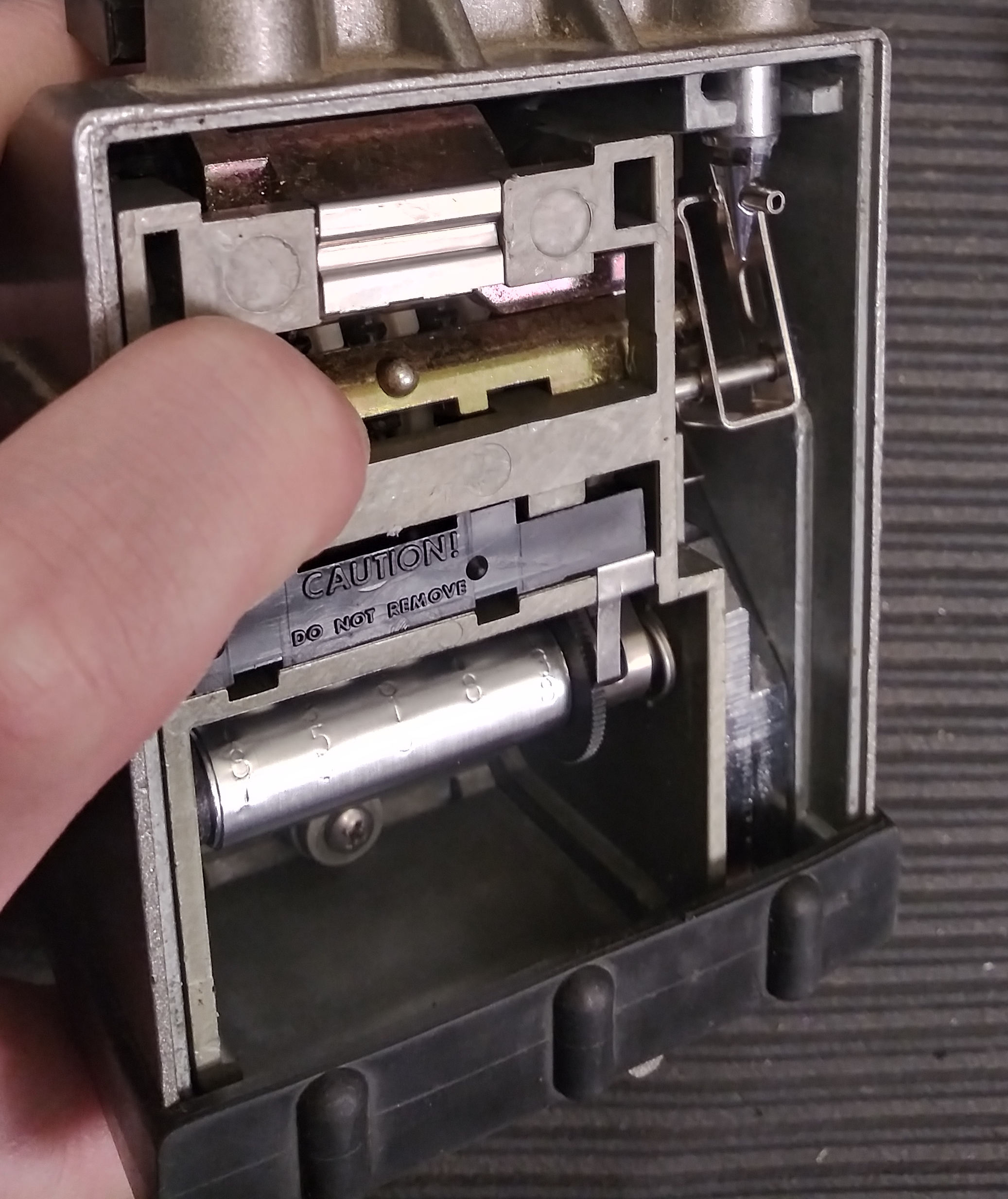
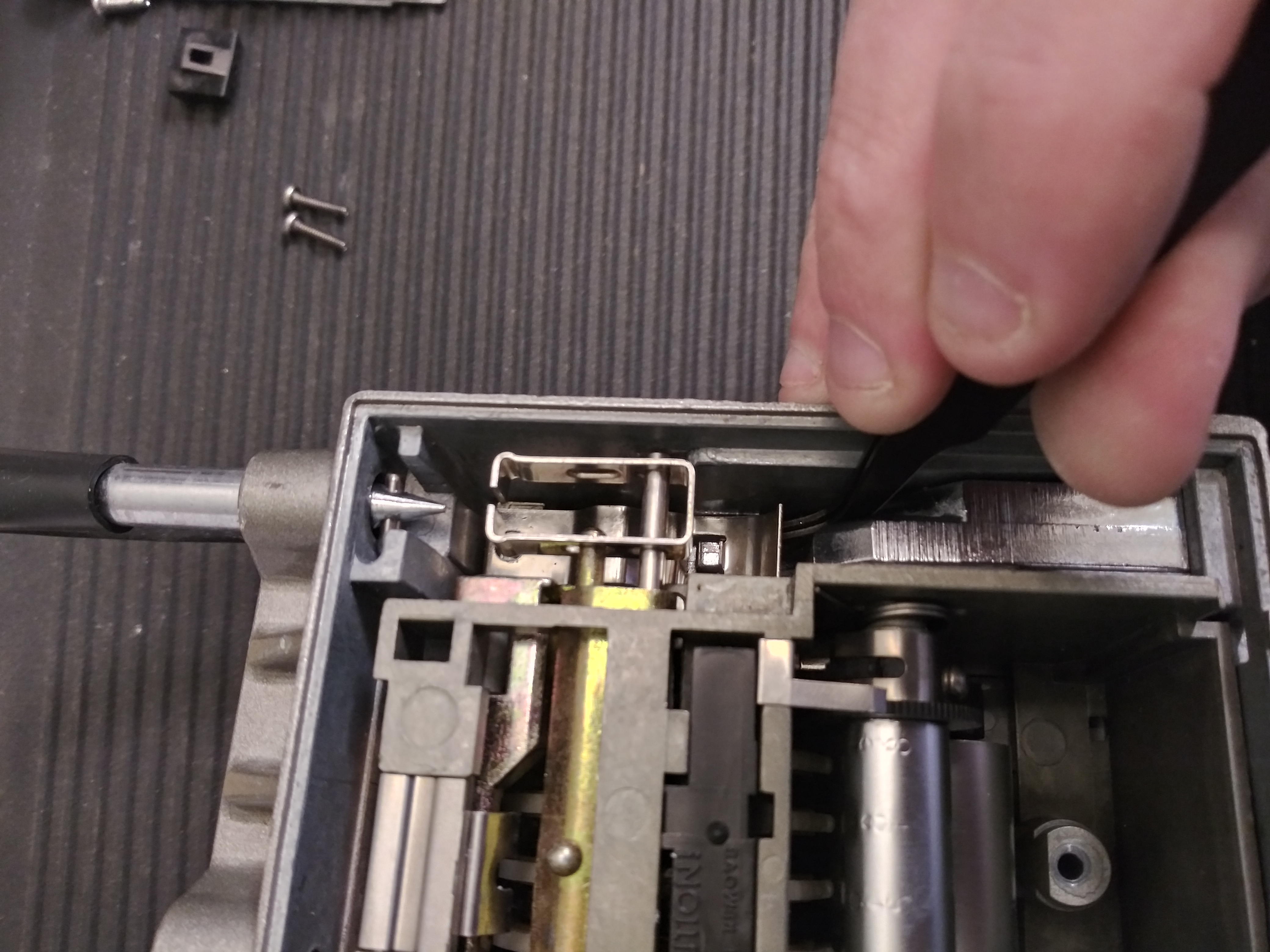
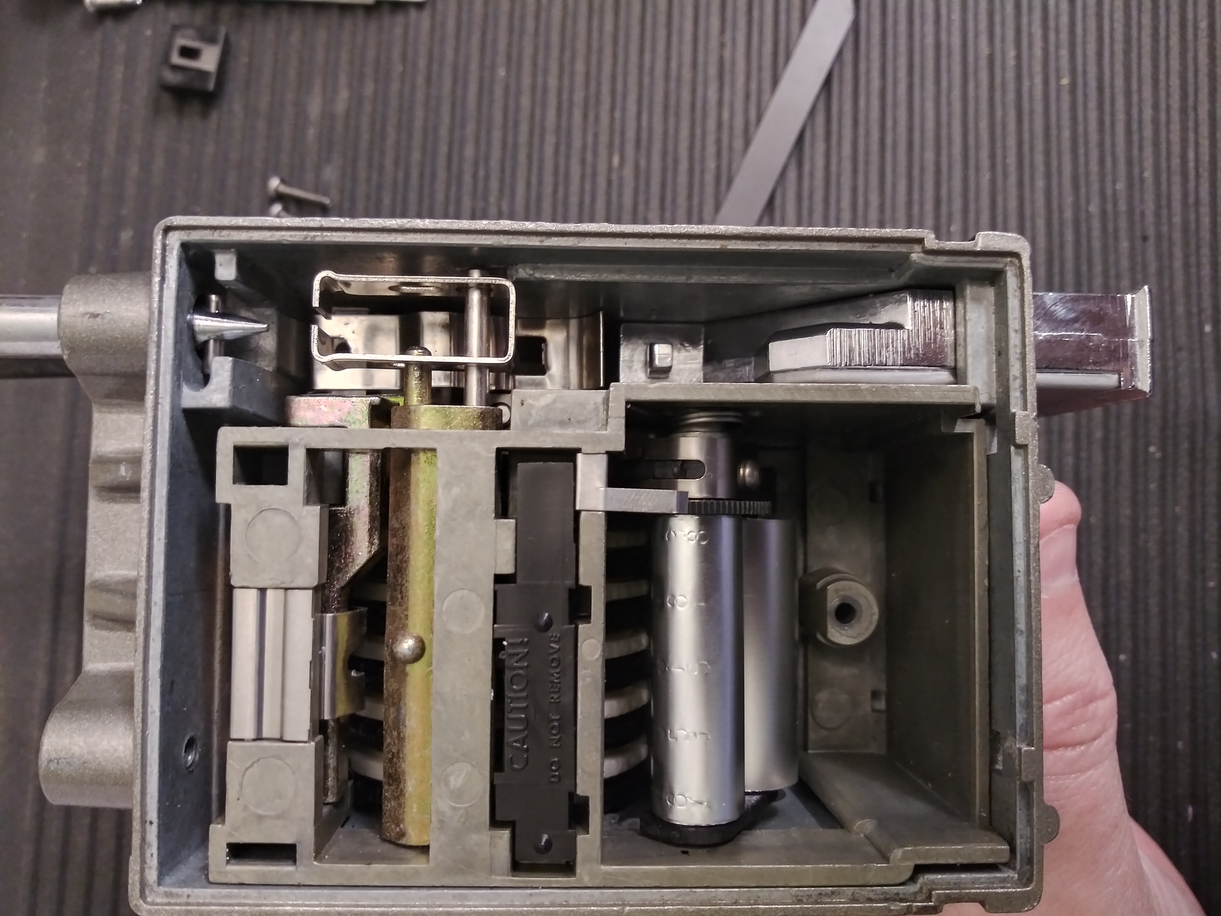
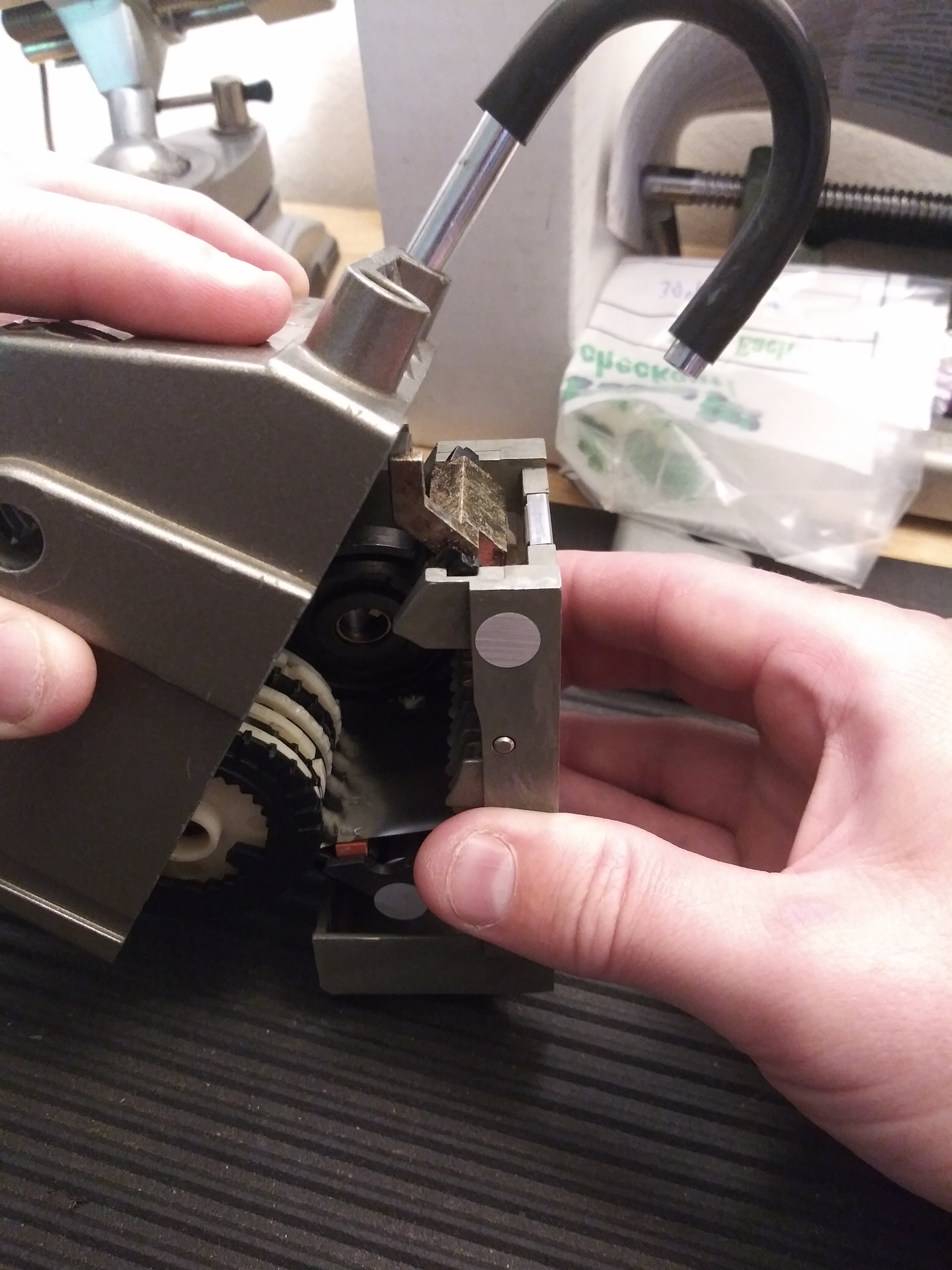
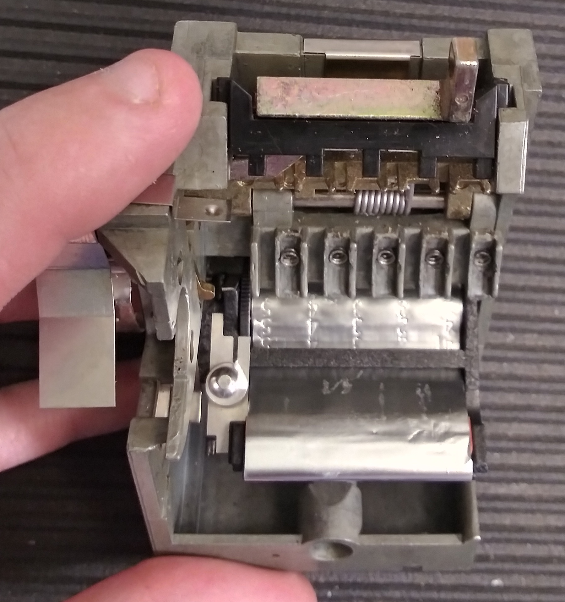
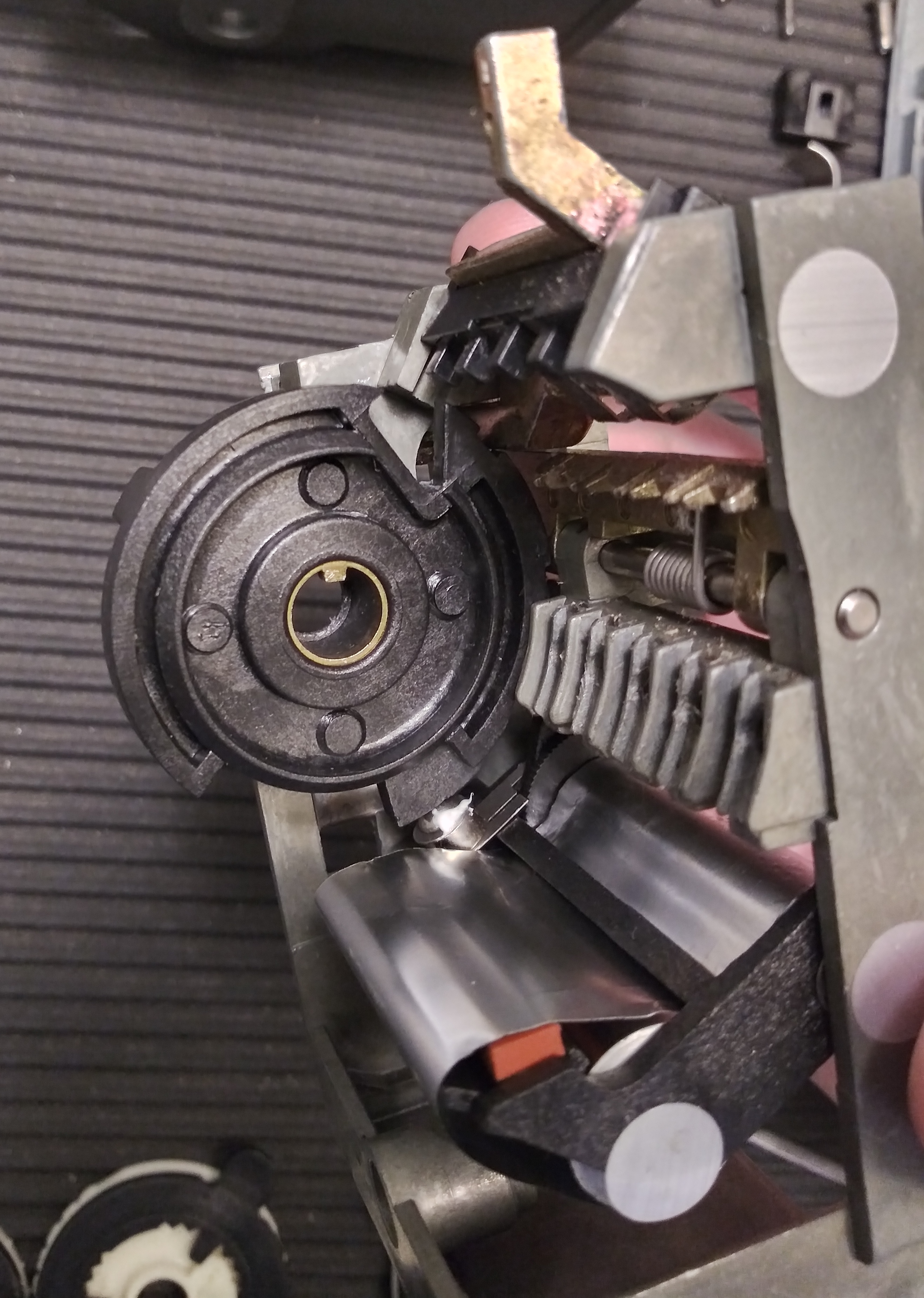
Now we can see the inner assembly of the lock. In this photo, the black-and-white sandwiched code wheels and combination rings are visible
between the copper-colored keybox release mechanism, top centerish, and the brass-colored shackle release mechanism in the middle
centerish. Below the shackle release mechanism is the black plastic cover for the combination ring detent springs and ball bearings,
below those the foil audit trail that records the bittings of keys that were used to try to open the box.
On the right-hand side, we see the shackle retaining clip (with shackle inserted,) and behind that the keybox-retaining spring leaf latch.
The keybox itself is located bottom right and extends upwards to the spring latch.
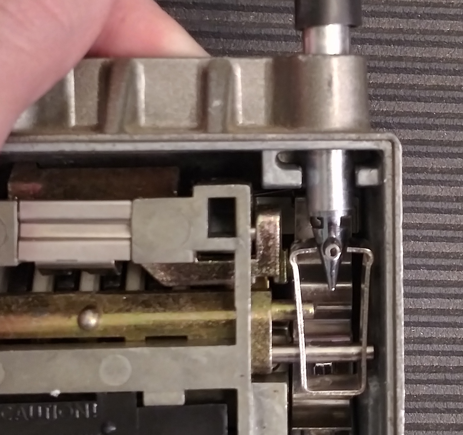
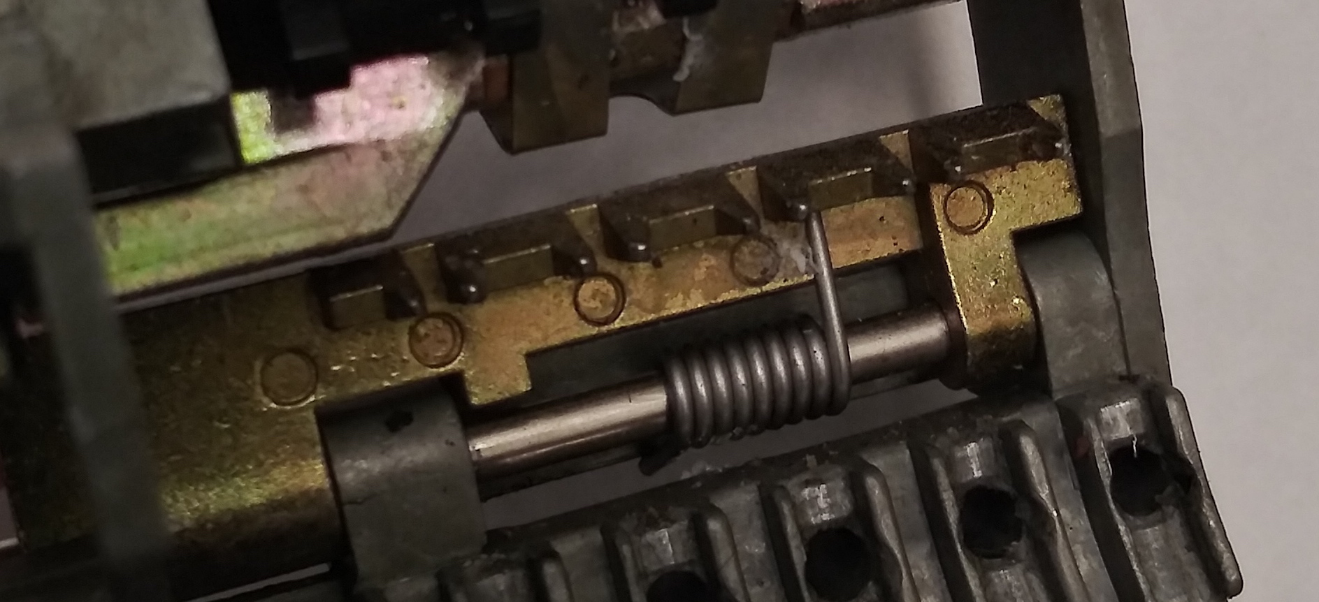
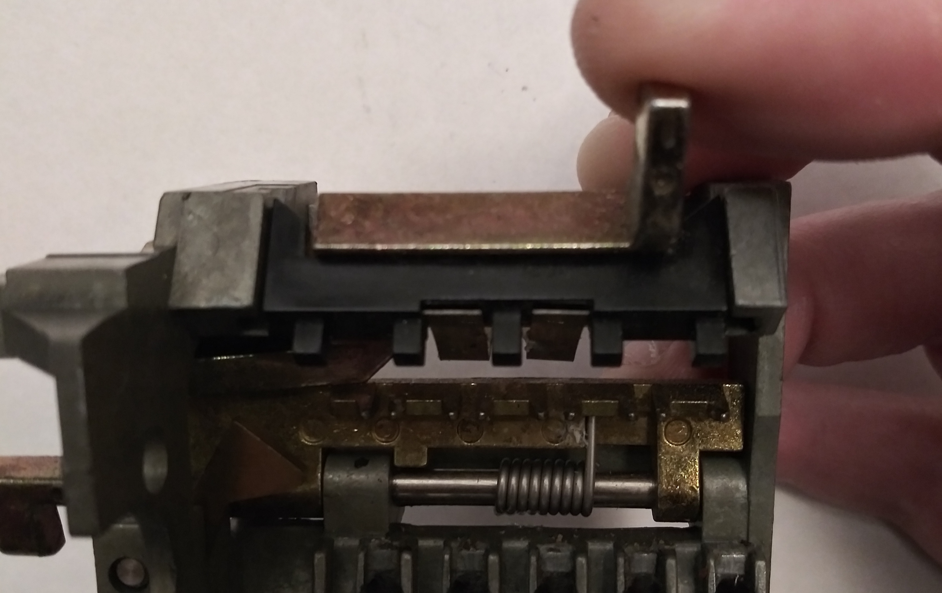
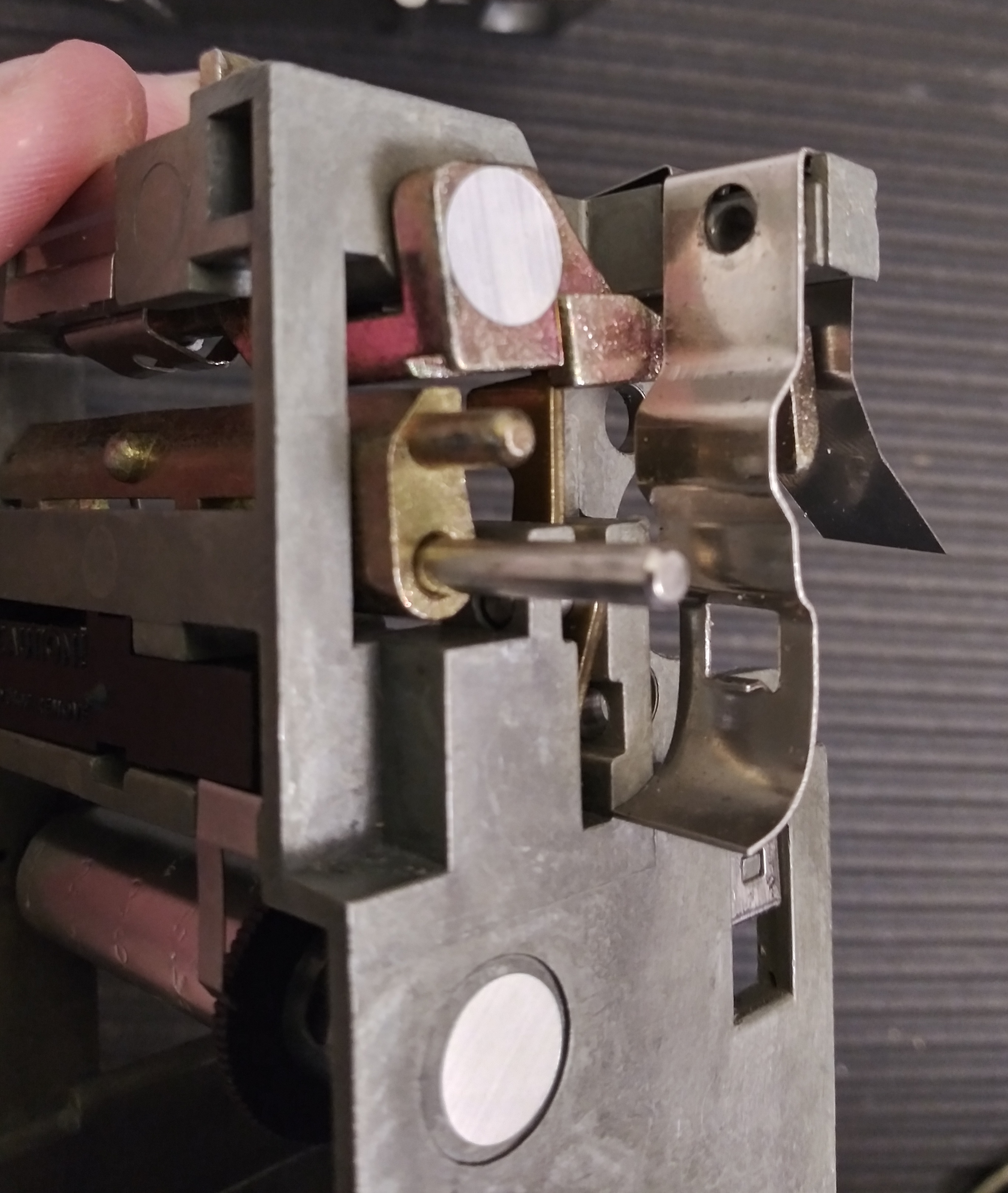
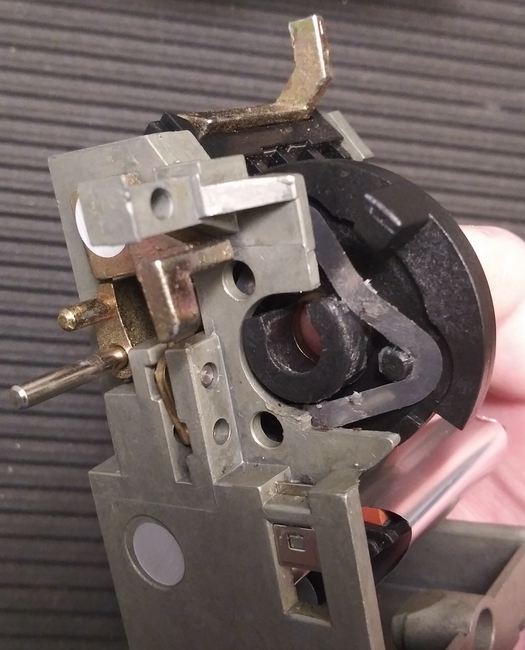
So how does the shackle release mechanism work? The shackle tip is tapered to spread the tines of a metal clip apart, with notches in
the tip that serve to capture the shackle once it's pushed in. To release, the metal clip is tilted at an angle until the tines no longer
capture the notches. This can only happen when fences on the shackle release bar are lined up with gates on the code wheels, allowing the
whole assembly to tilt when the shackle release button is pressed.
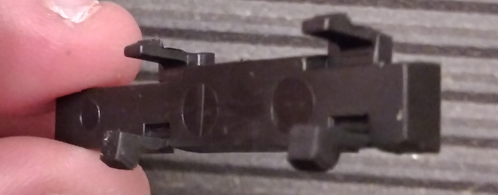
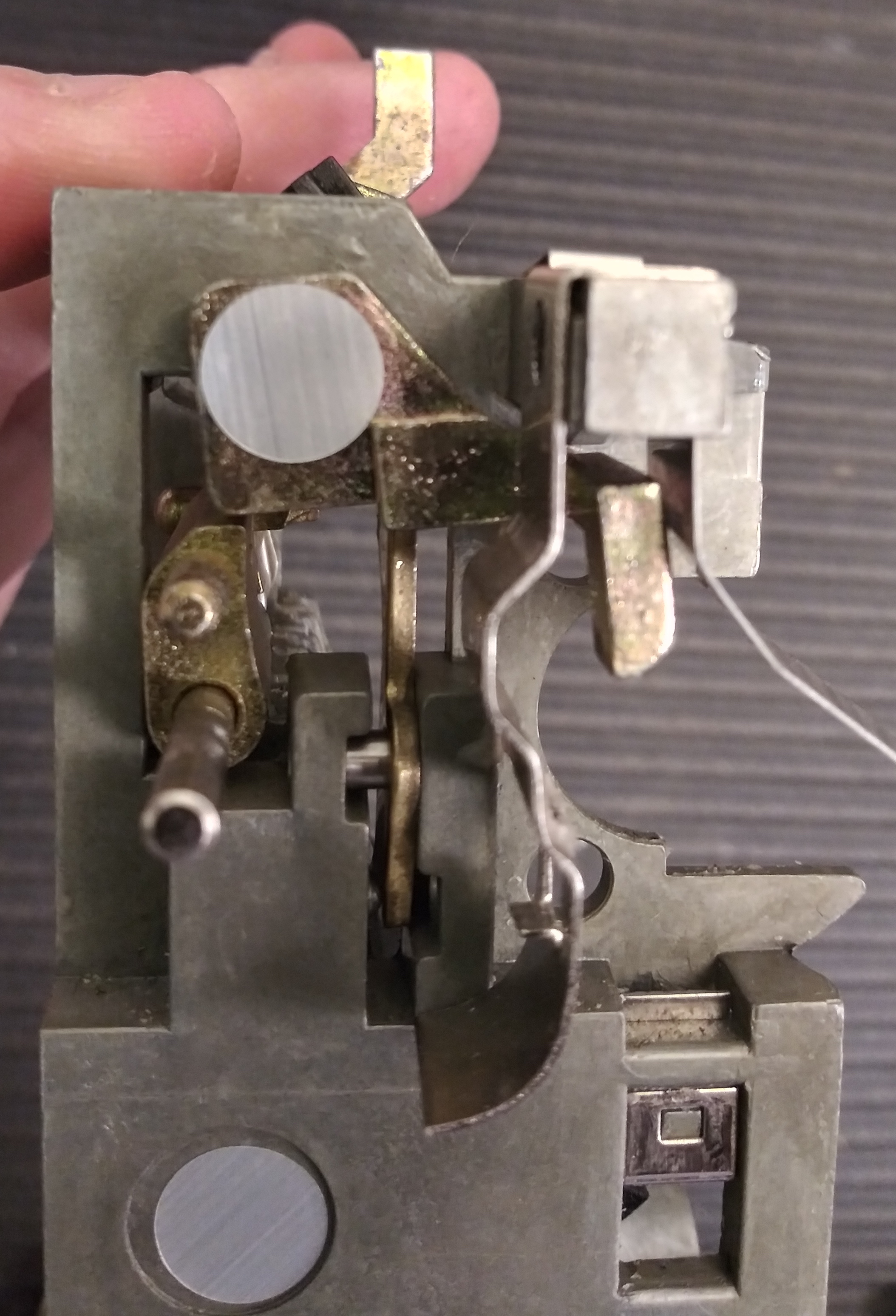
The shackle release fences as seen from the inside, with two prongs on the sides.
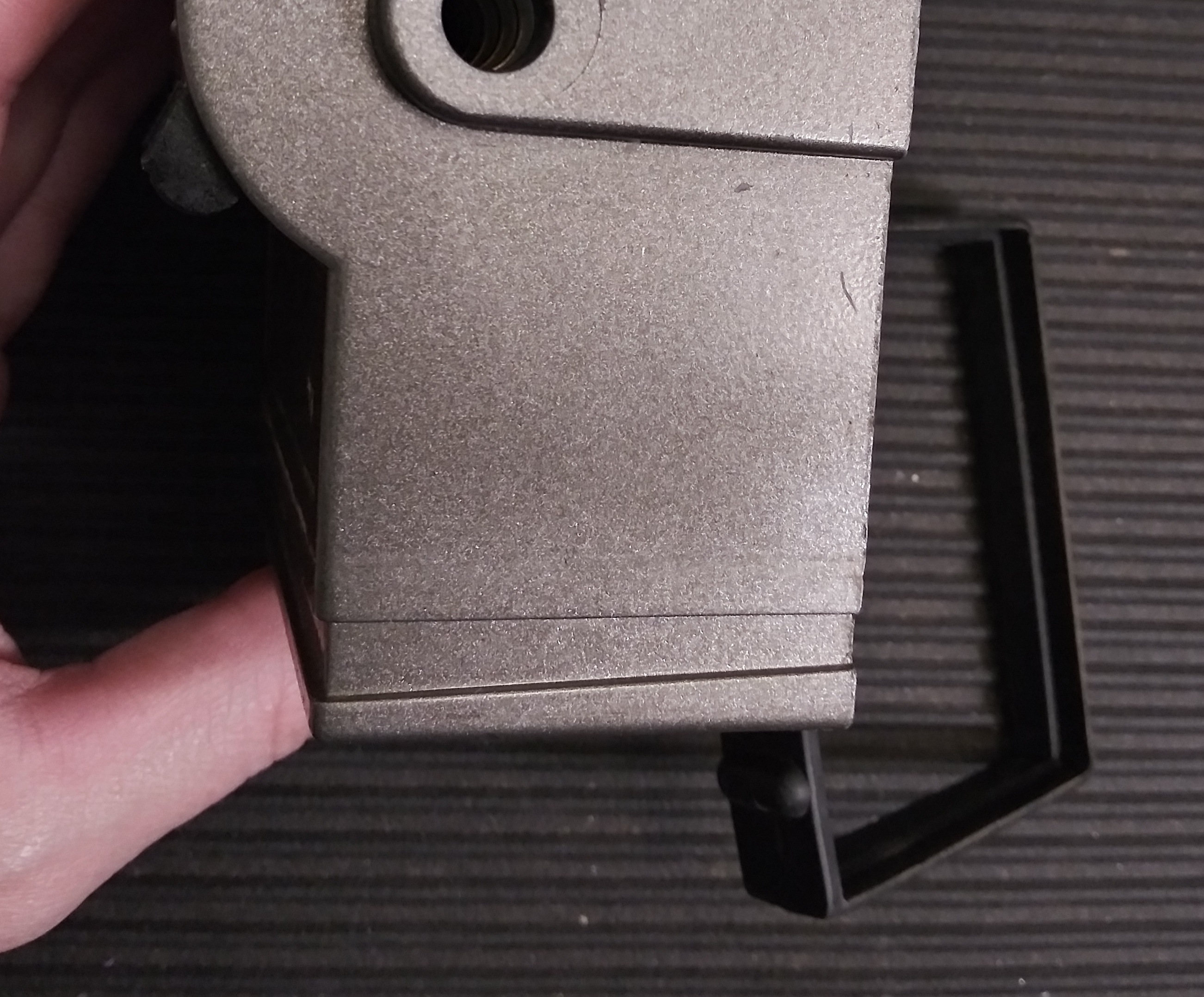
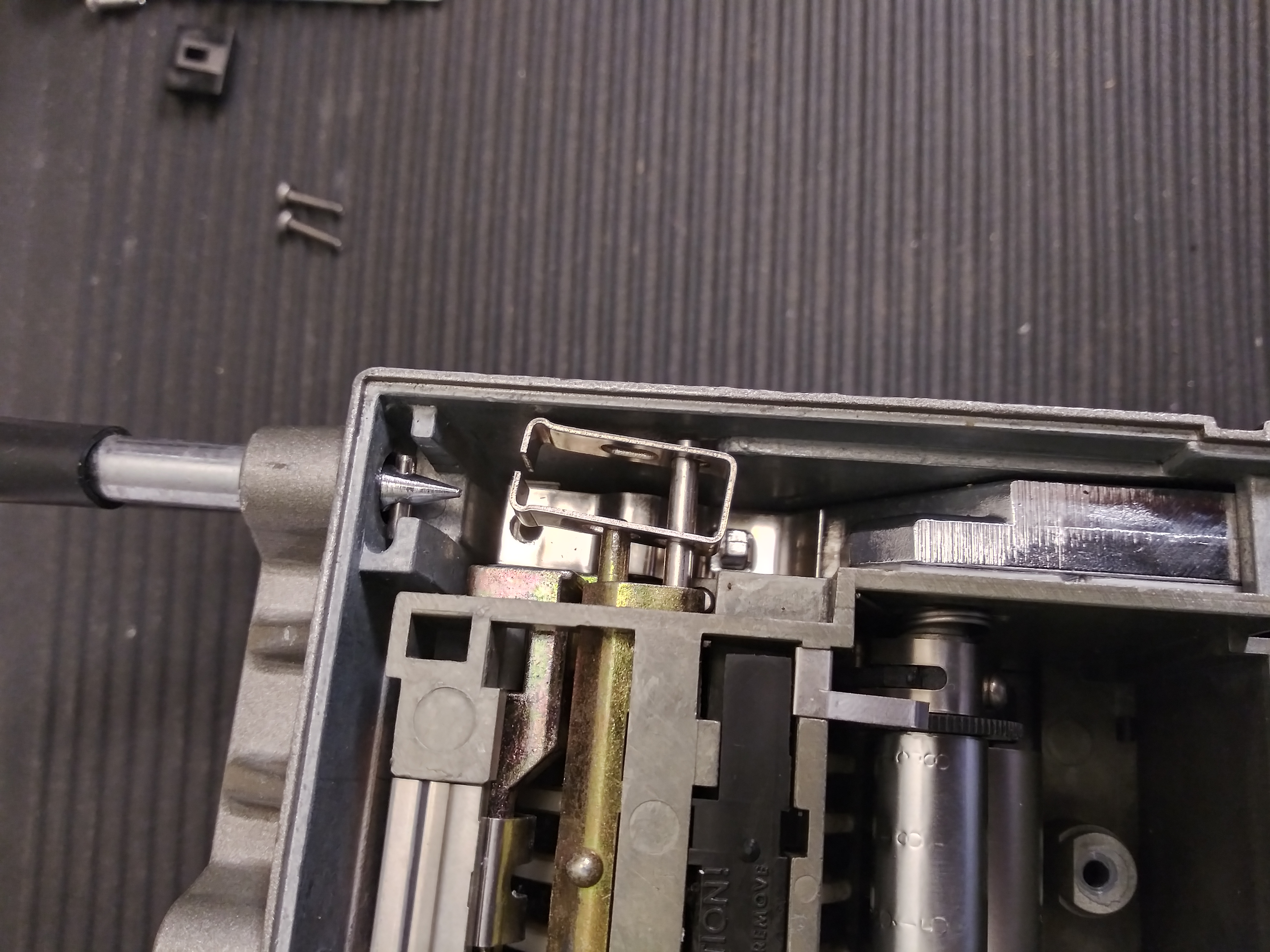
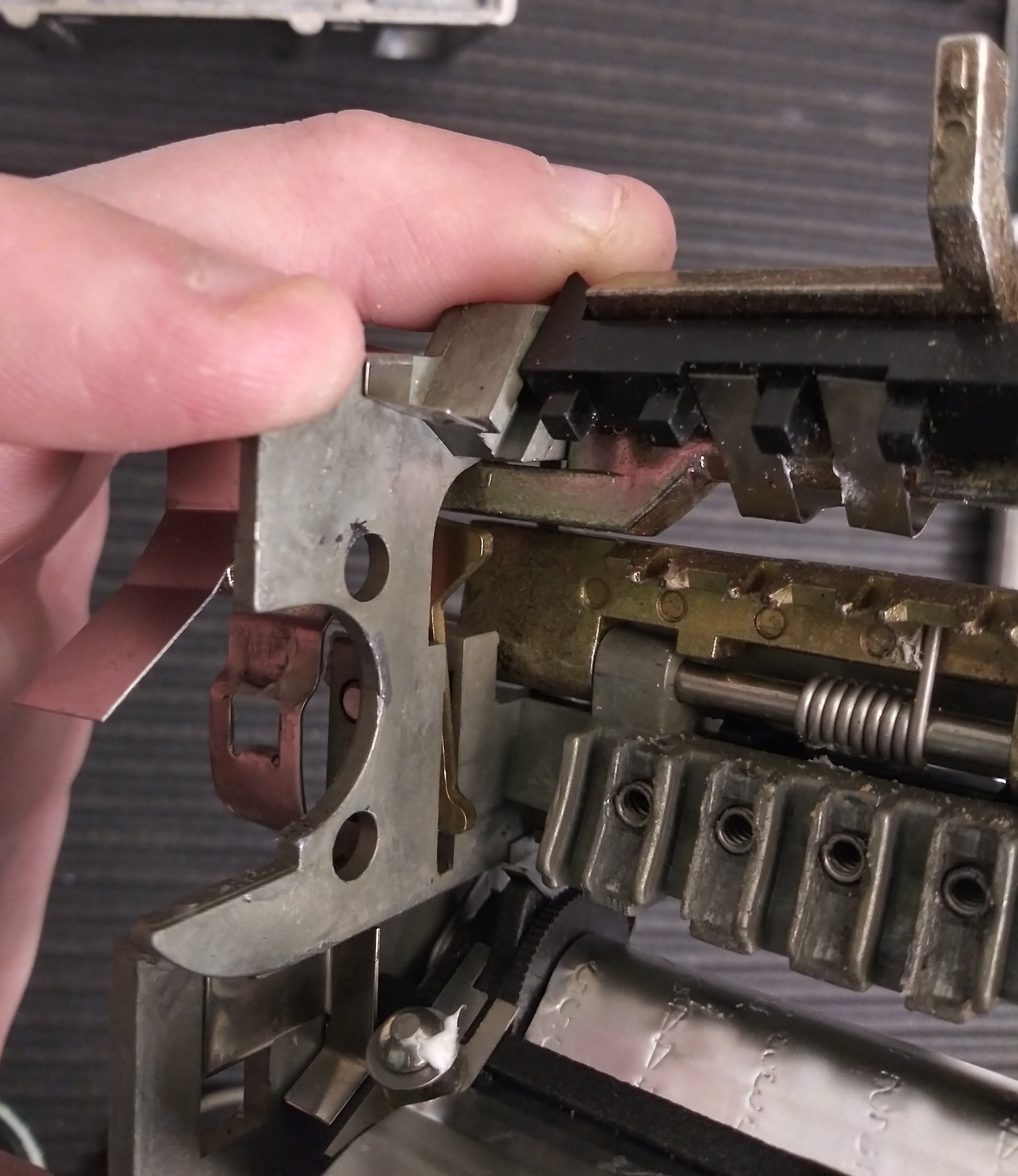
How is the keybox retained? With a single spring leaf latch, no deadlocking mechanisms included. This may have been the source of their
destructive entry problems.
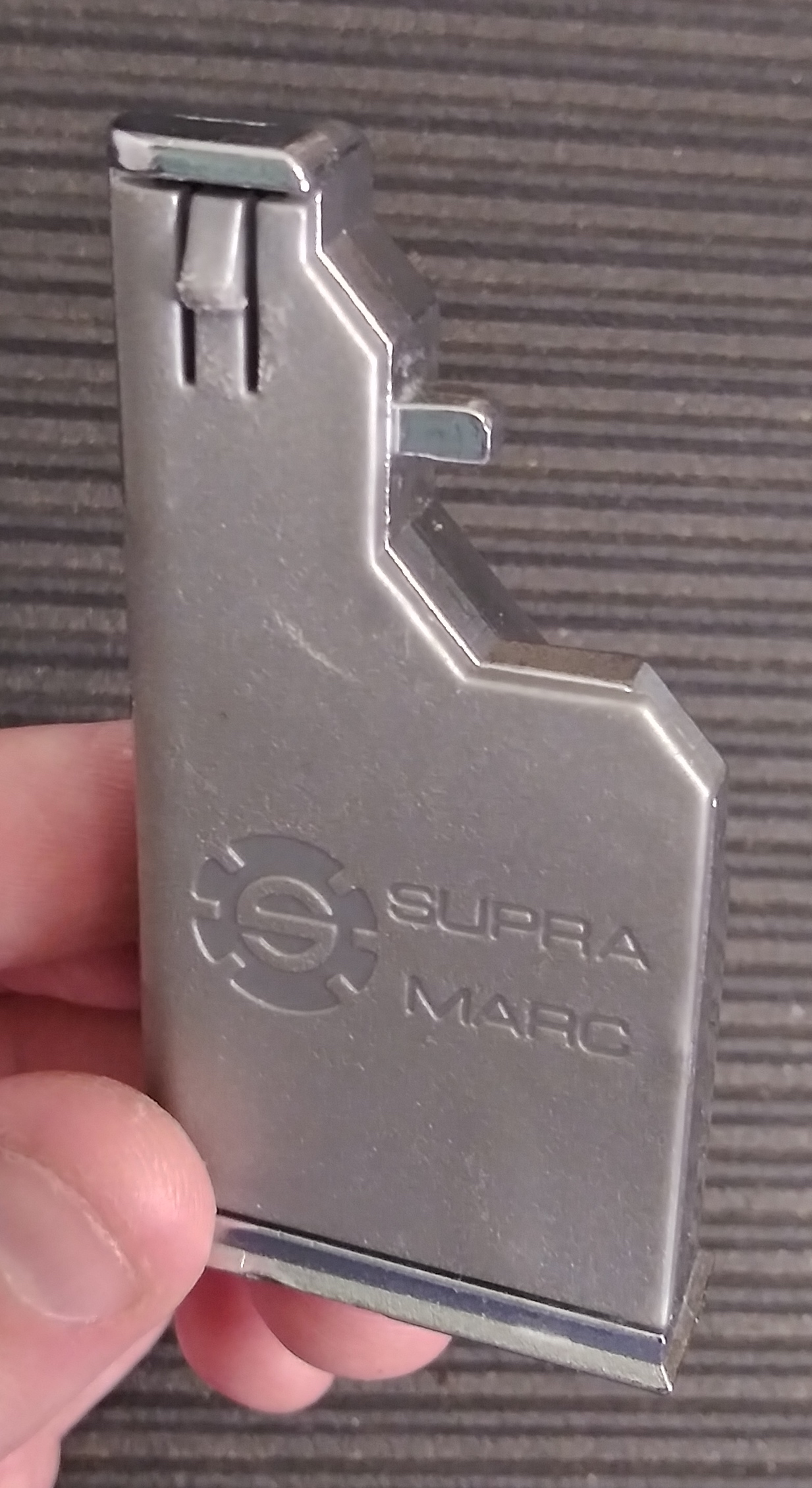
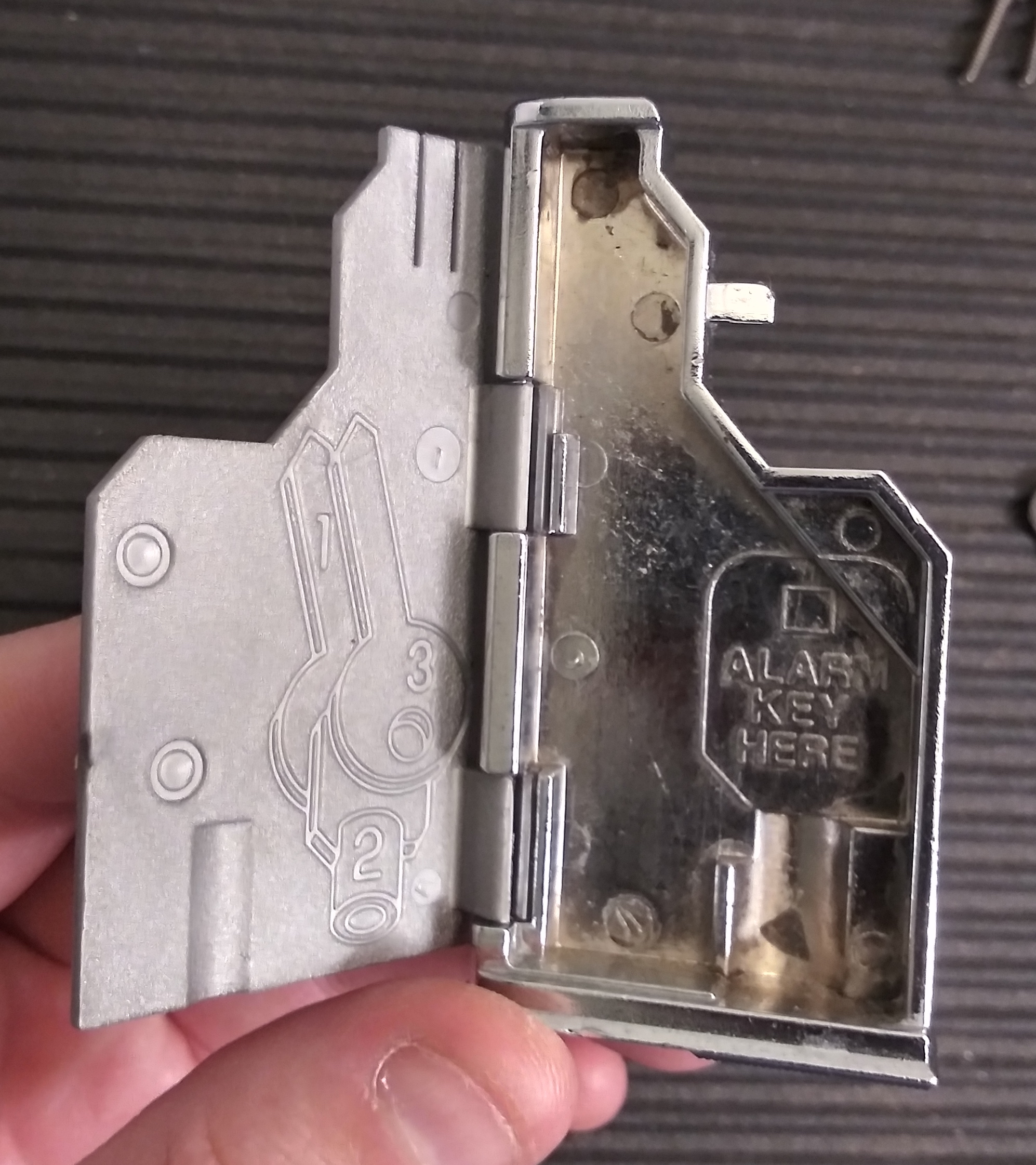
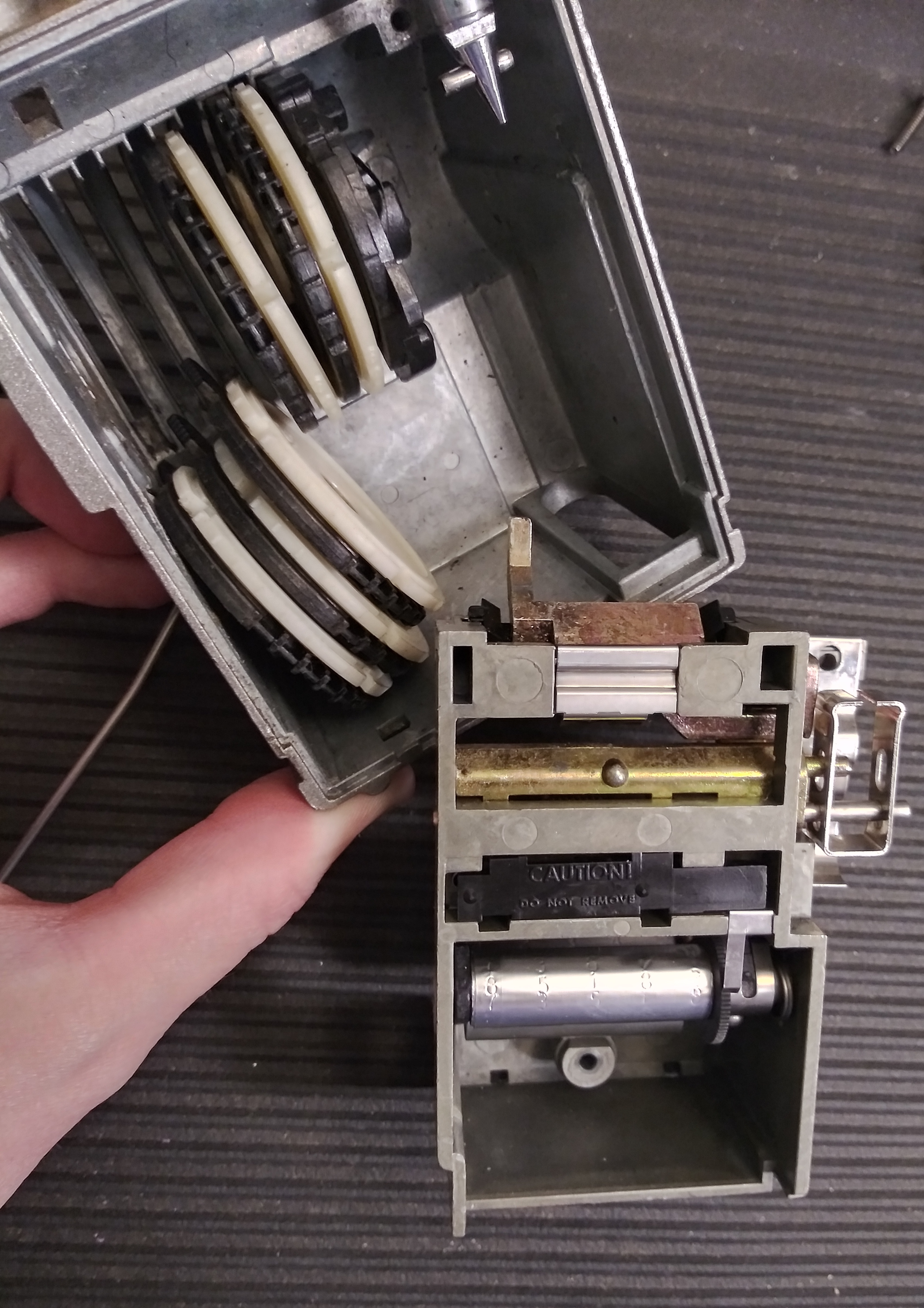
We can remove it by prying the plate gently upward with a screwdriver and pulling the keybox out from the bottom of the unit.
It's a very pretty keybox, though! Quite spiffy.
This is as far as you want to go with disassembly. Seriously.
How does the keybox locking mechanism work? Well, we need to disassemble farther to find out. I highly recommend not dissassembling
yours beyond this point — it's not necessary if you're trying to decode the lock, it's fiddly as heck and I went about things in the wrong
order. If you're determined to do so, here's the process I'd recommend now. You'll see that photos are out of order and won't exactly
reflect a linear process.
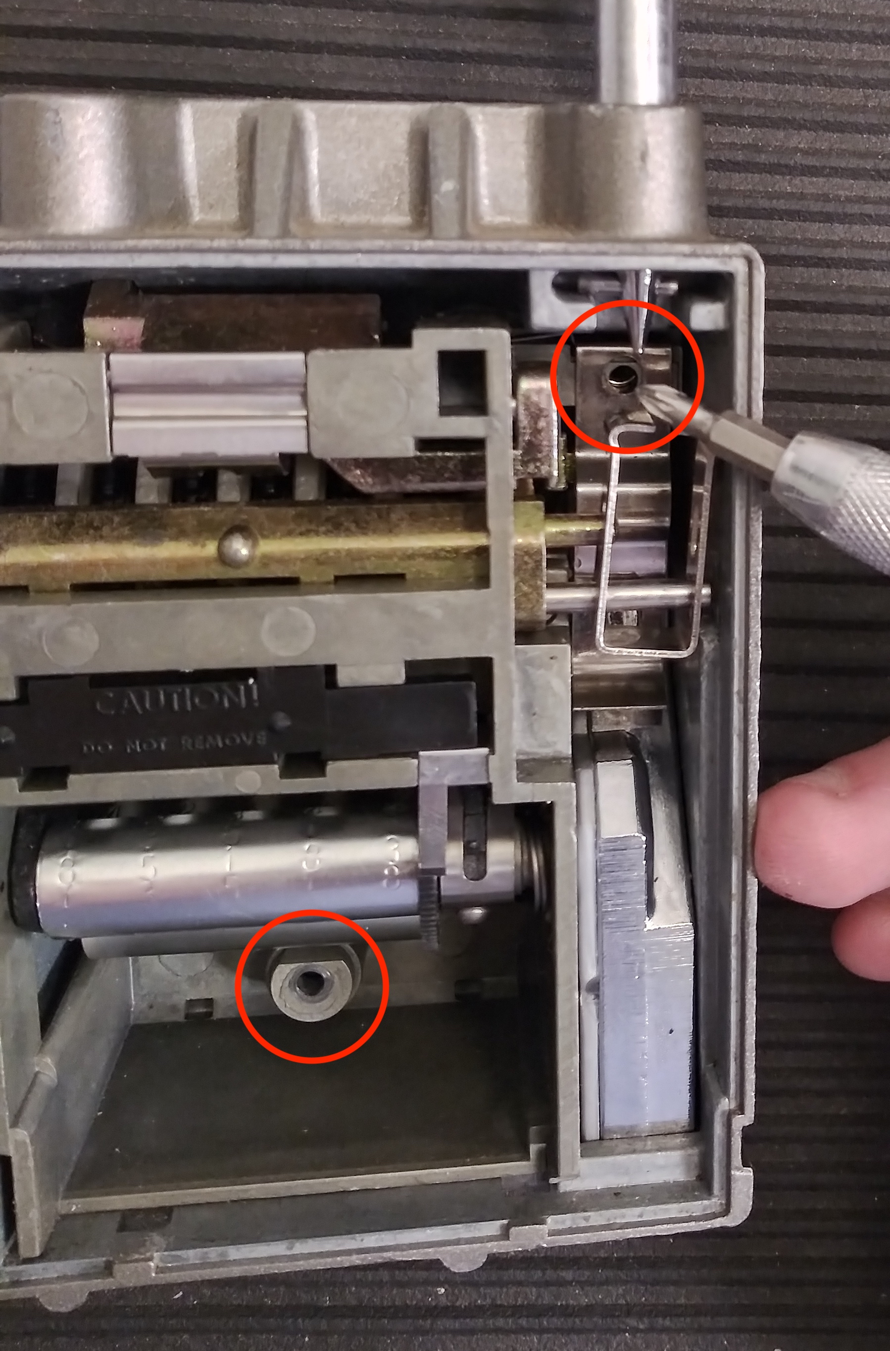
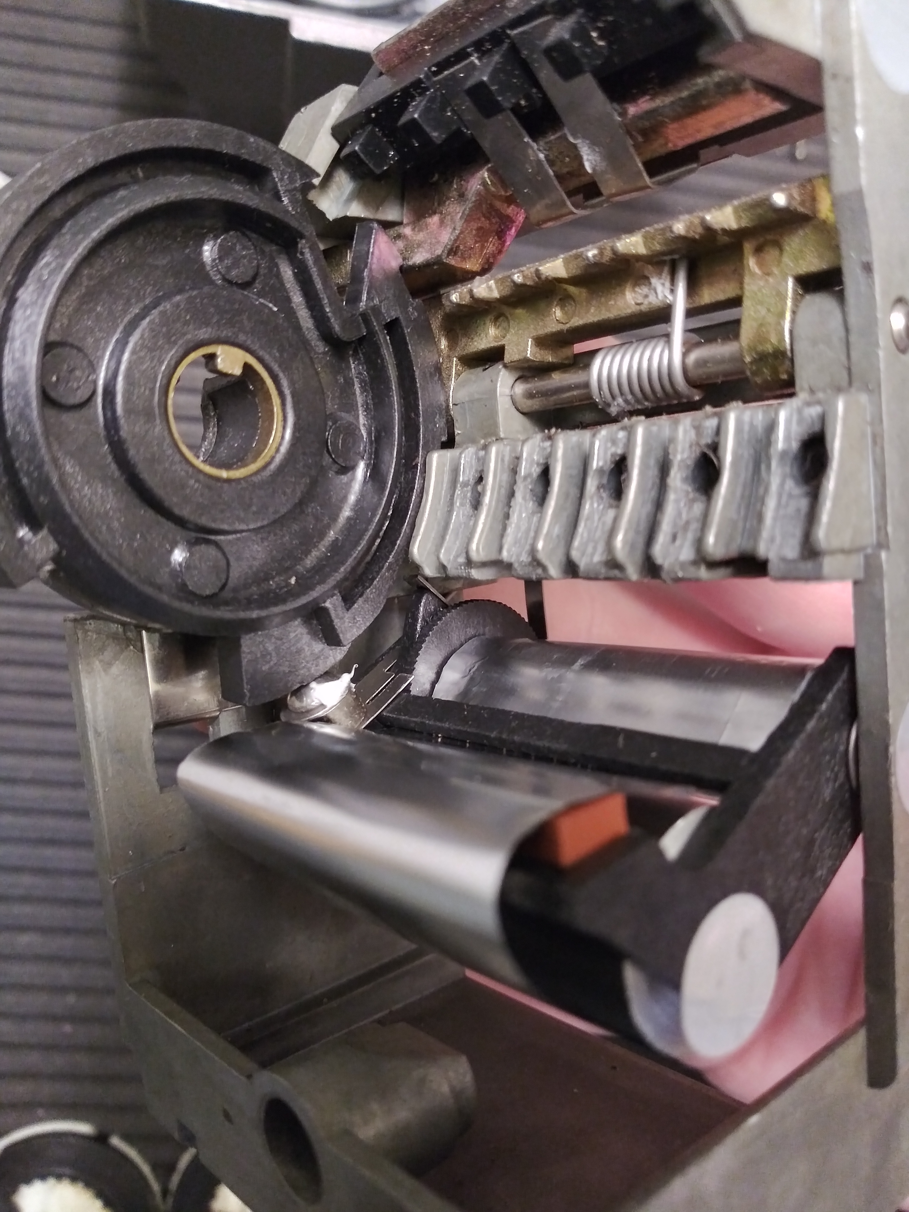
It's easiest to remove the inner assembly if the keybox actuator can be fully depressed, which means decoding the keybox opening mechanism.
In particular, we'd like the numbers for keybox opening to be as high as possible. This can be accomplished by using some kinda tooling to
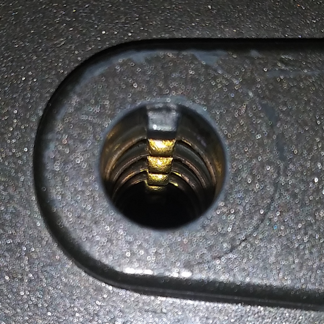
rotate the code wheel inner lugs clockwise by ideally 1-3 positions, putting the possible true gate ranges (5-10) within reach. The inner
lugs for the code wheels are only the first 5 brass lugs seen in the keyway, the 6th and last belongs to a "sequencing wheel."
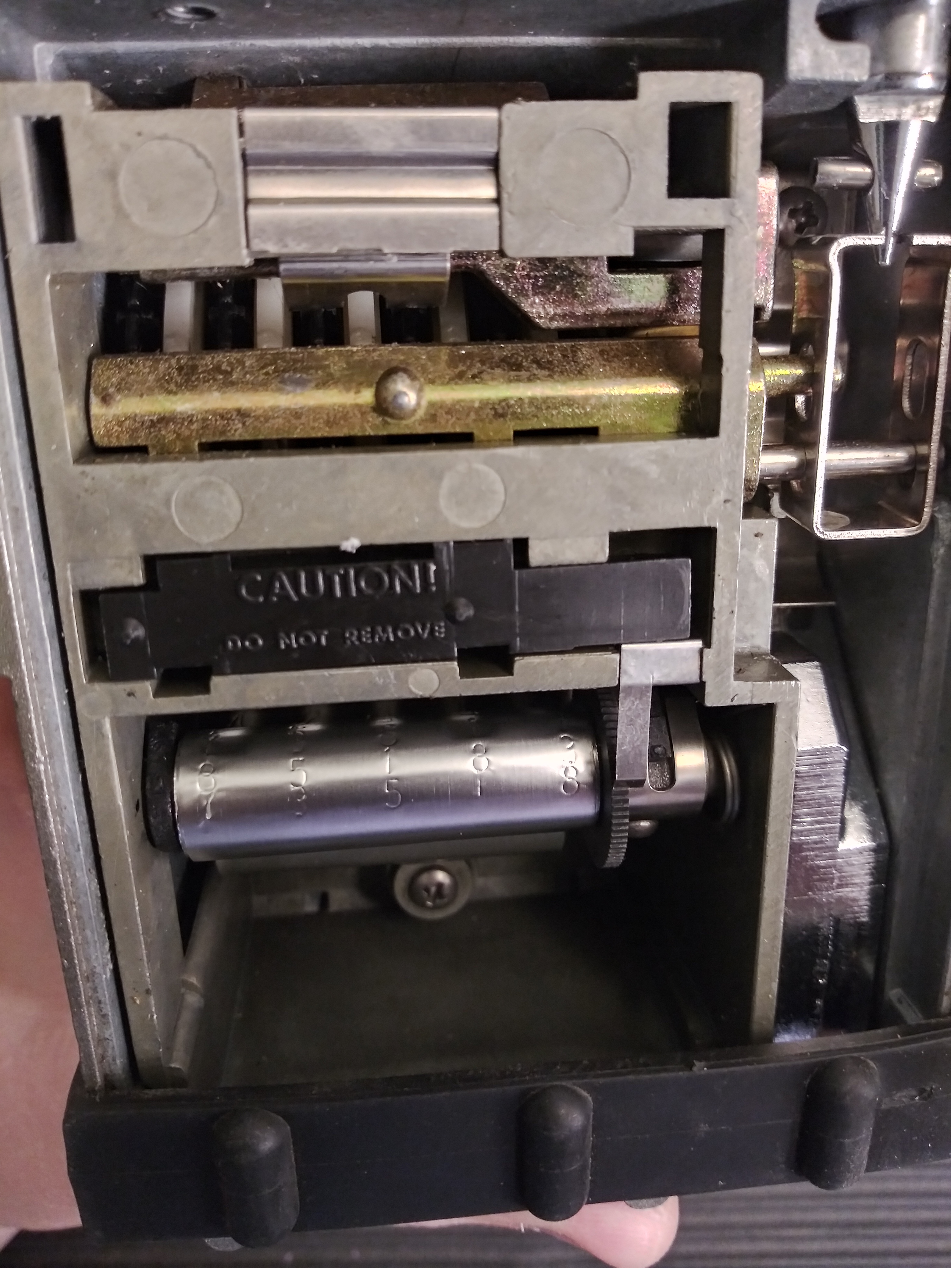
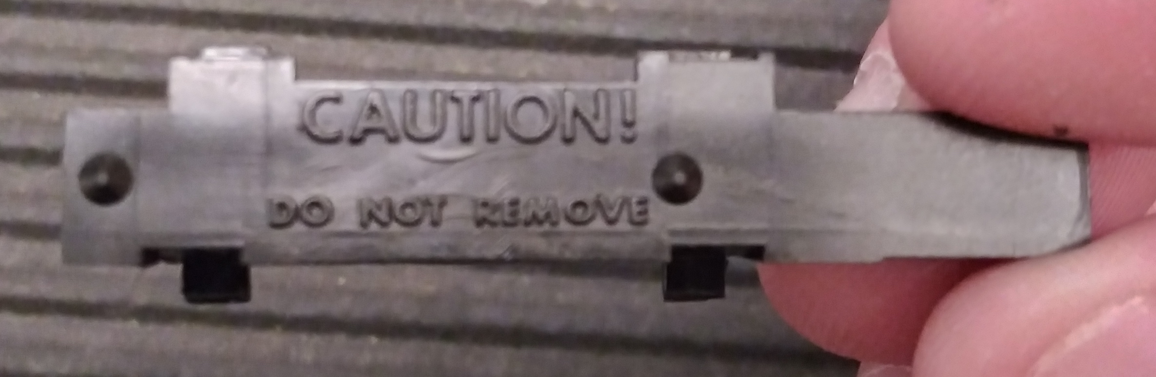
Next gently remove the DO NOT REMOVE plastic cover, being aware that strong springs and ⅛" ball bearings are behind.
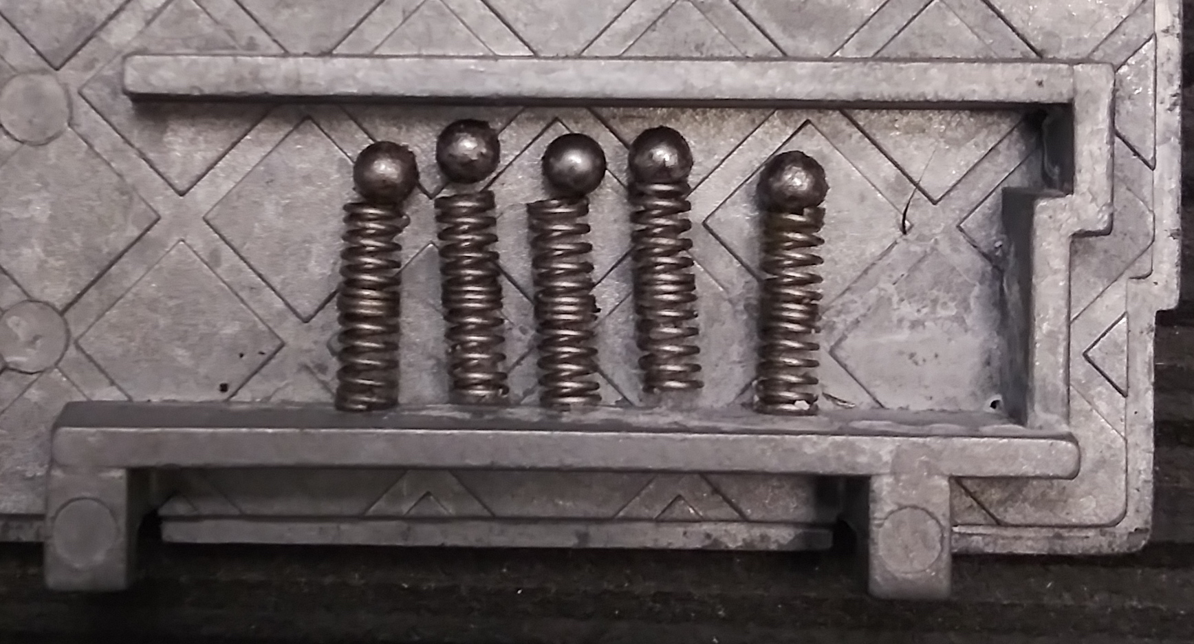
Remove the springs and bearings; these function as detents for the combination rings.
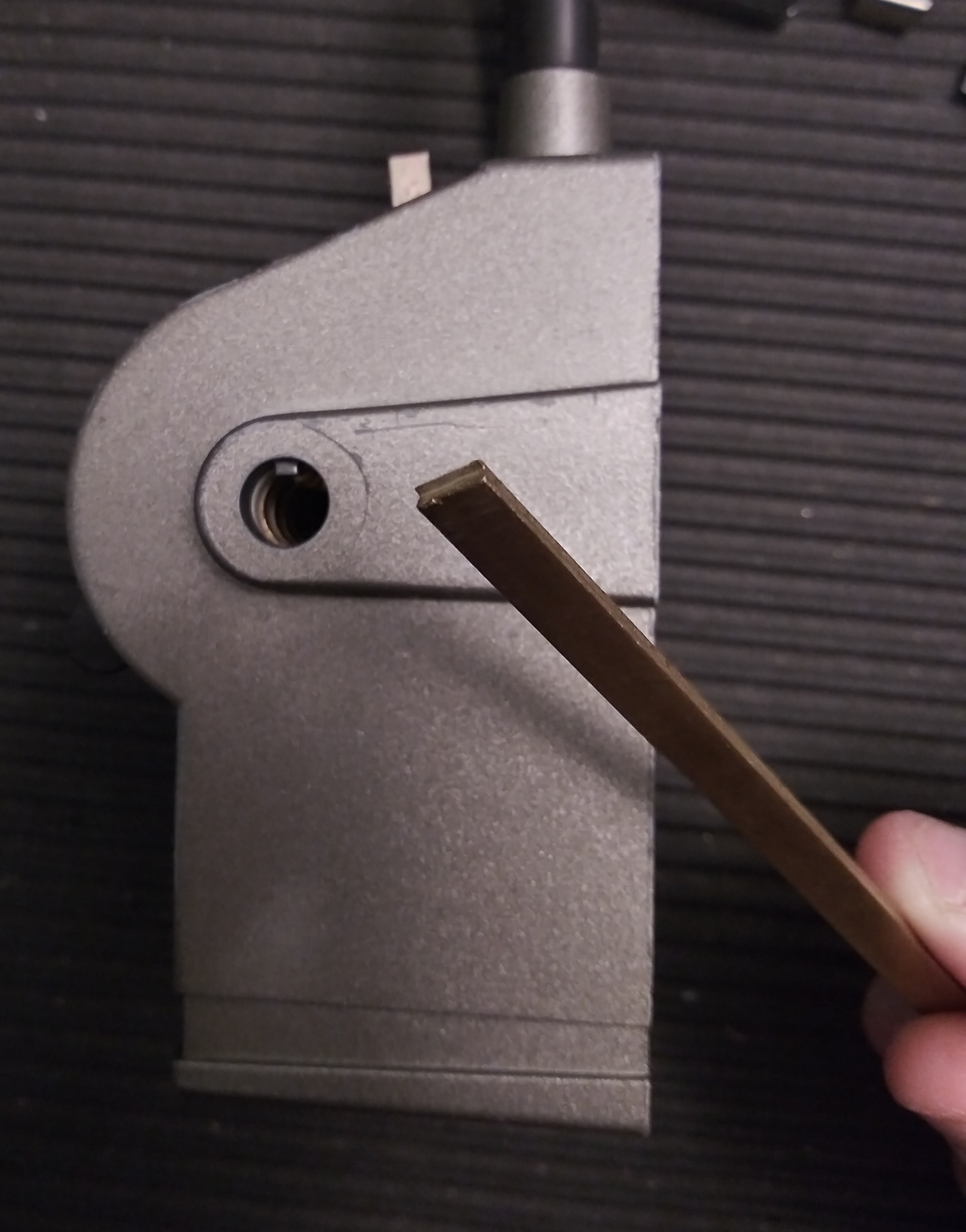
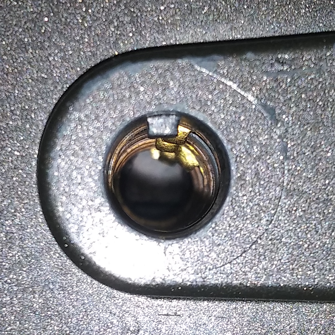
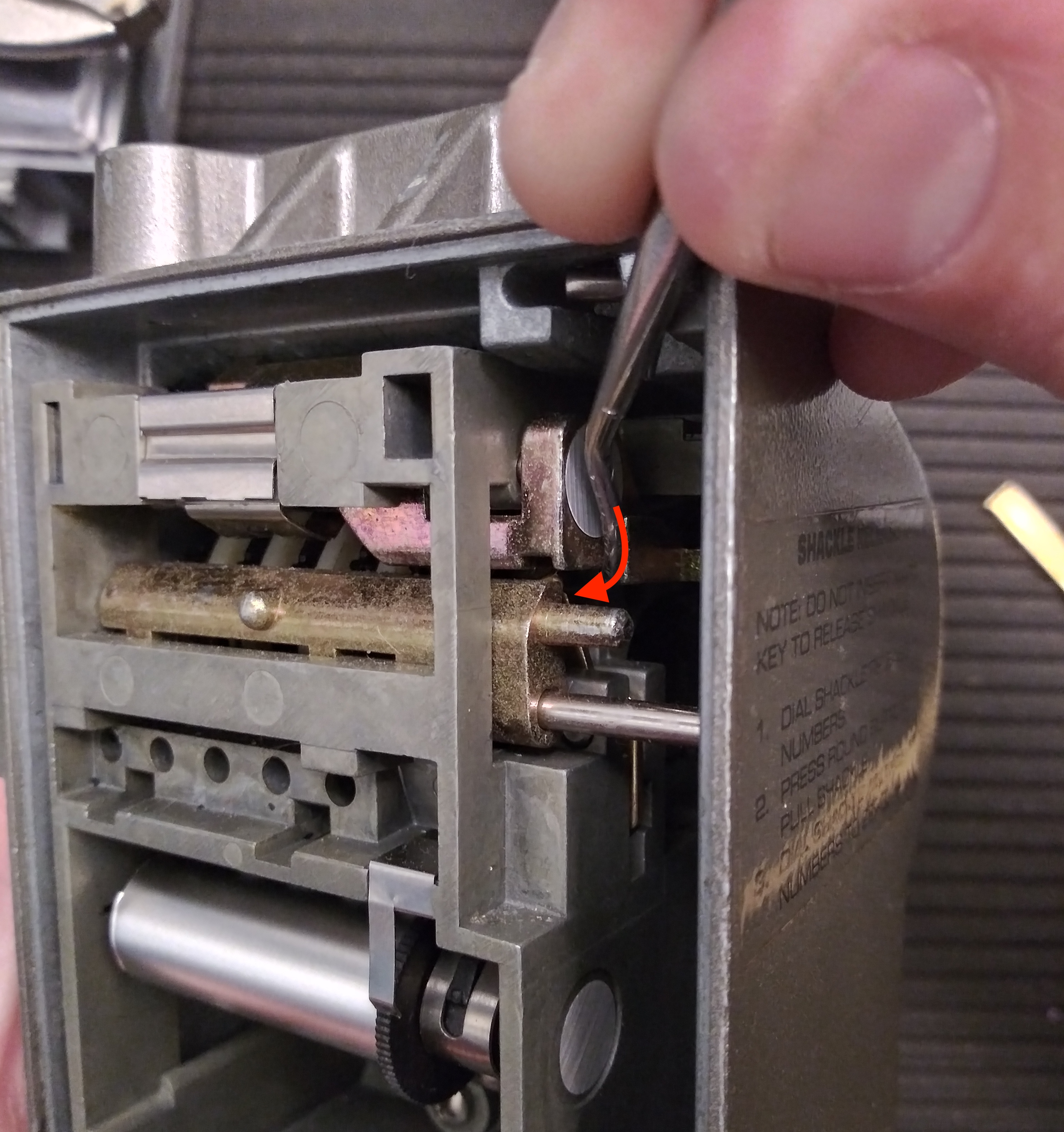
Now mimic the process of opening with a key; we will gently and firmly rotate the back sequencing wheel using that 6th and farthest lug
in the keyway, rotating about 39 degrees clockwise and feeling spring resistance in the last bit of rotation, then push inwards (hearing
a "snap".) This will line up the cutout in the sequencing wheel for the keybox actuator blocker, which we push the top of to rotate
and clear out of the way of the keybox actuator bar. Now the actuator can depress enough for the fences to contact the code wheels.
Depress the keybox actuator and decode the combination using the same process you used for the shackle release code. The tabs on the
combination rings will move freely as the detents no longer snap them to whole numbers. Remember the combination you find.
Lift off the keybox actuator plastic cover (it's just pressed on.)
Remove the two screws retaining the inner assembly, one bottom center and one top right.
Keeping the inner assembly vertical, fully depress the keybox actuator and hinge the outer shell upward and forward, pivoting from the top.
Be aware that parts will start falling out, this is OK, we can put them back later. Just make sure the spring and ball bearing
for the keybox actuator blocker don't go anywhere (they're pretty solidly retained, this is unlikely.)
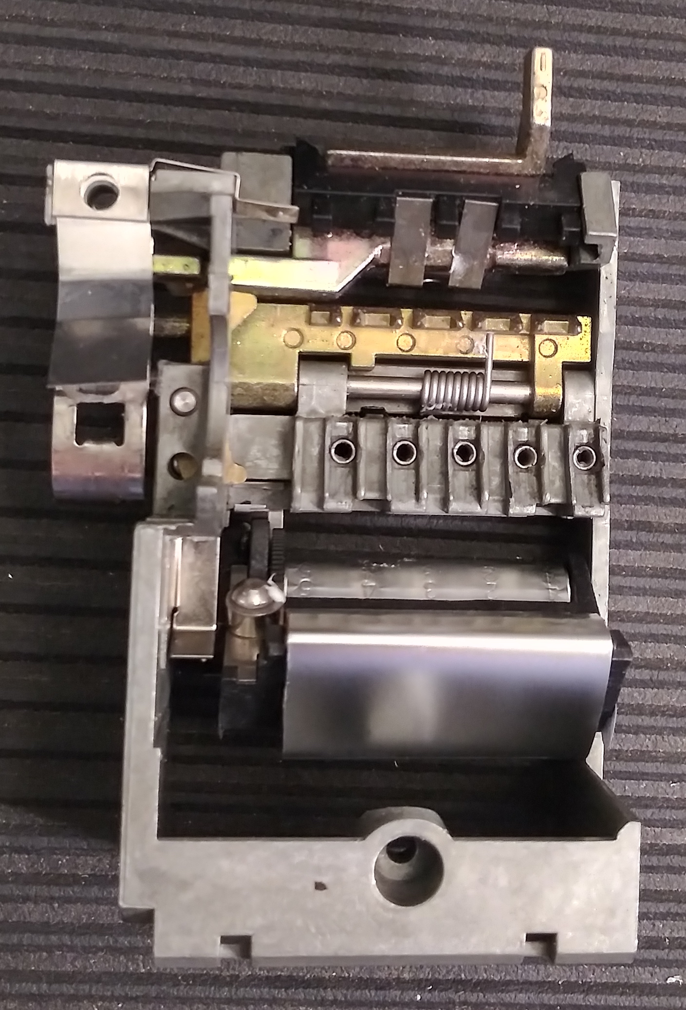
Congrats! The guts are now in your hands, and we can get a better sense of how the keybox locking mechanism works.
Keybox retaining mechanism
Fully depressing the keybox actuator lifts the keybox-retaining spring leaf latch directly. The bar connected to the keybox actuator
has two mechanisms that can prevent it from moving: direct-entry fences that need to be aligned with true gates on the code
wheels, and a blocker that will prevent the bar from moving far enough for the fences to even contact the code wheels, preventing
immediate decoding.
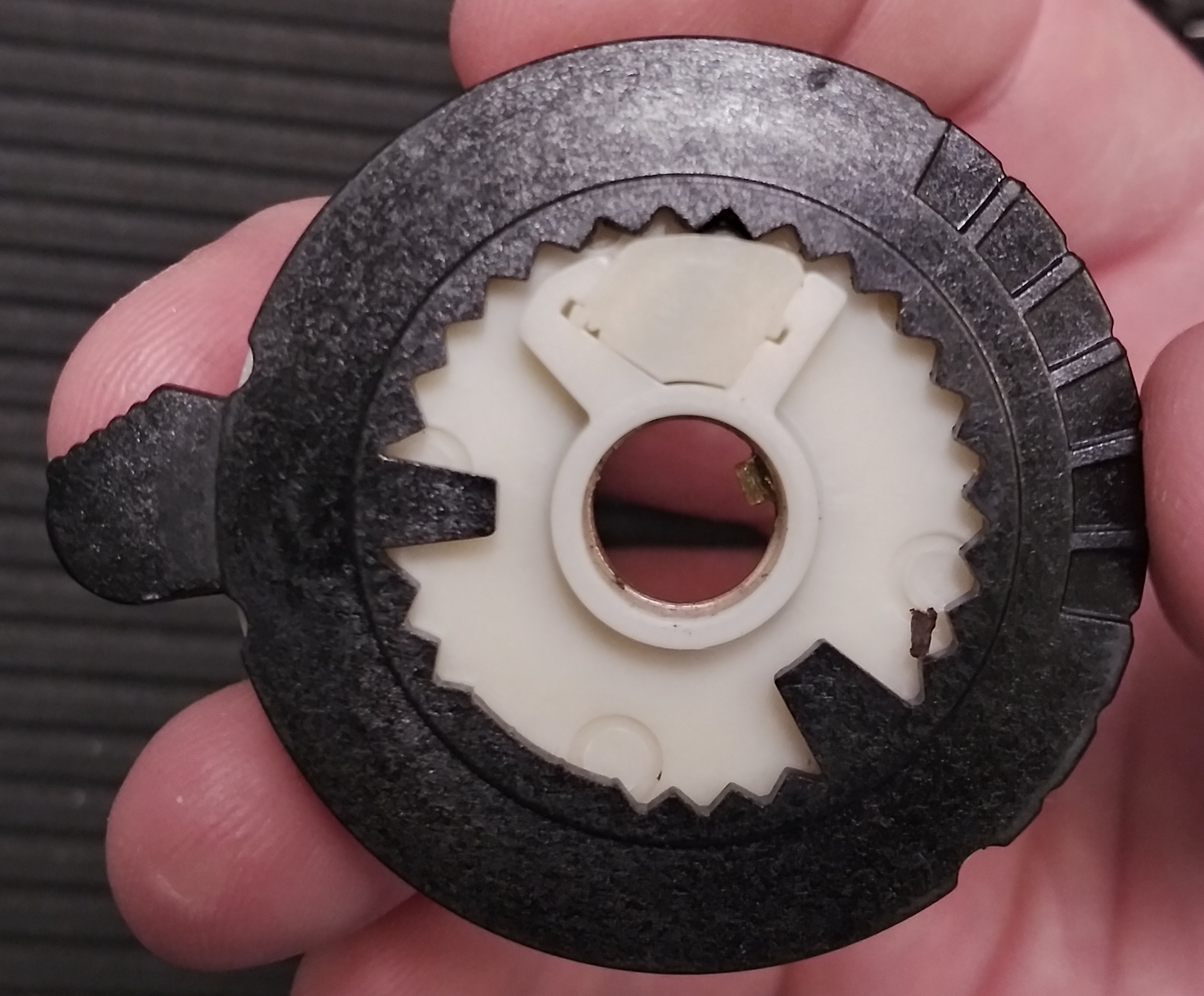
Code wheels
When depressing the keybox actuator (with the blocker cleared, we'll talk about that below,) black plastic sliding fences will
attempt to enter the code wheels.
The coded portion of the wheels is white; the rectangular cutouts are for the keybox actuator fences, and the angled cutouts are
for the shackle release fences.
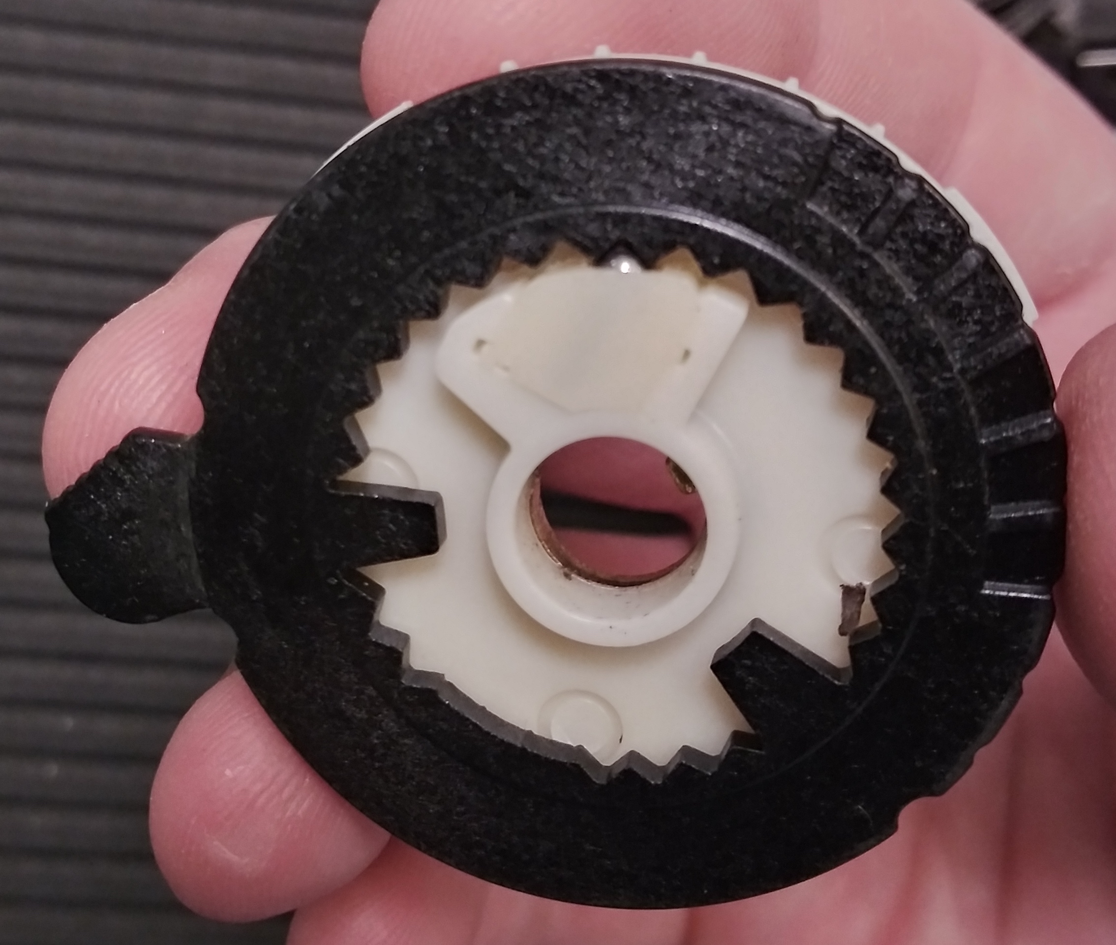
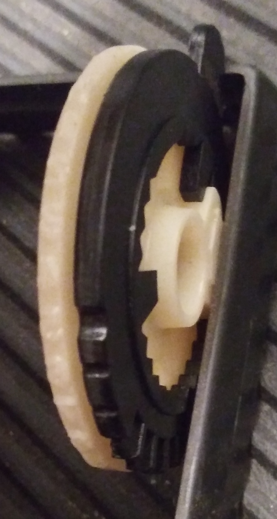
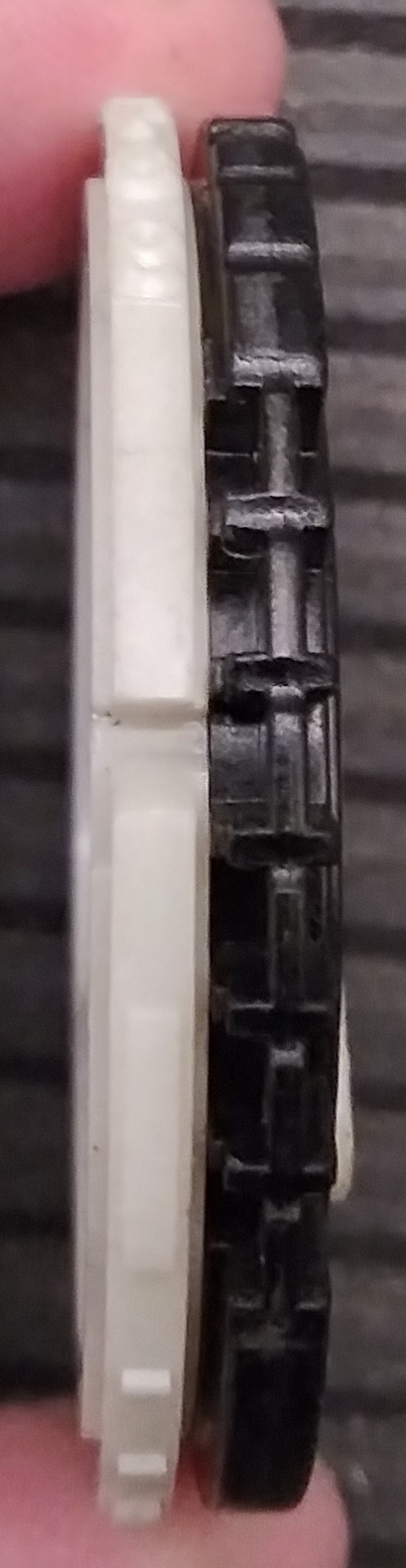
The code wheel assemblies have a sandwich construction that allows the code wheels to be moved forward by either the brass lugs
embedded inside the white coded portion or the attached black combination ring with the tab wheels. This is possible because the
strength of the detents holding the combination ring in place exceeds the strength of the detents connecting the wheels
themselves.
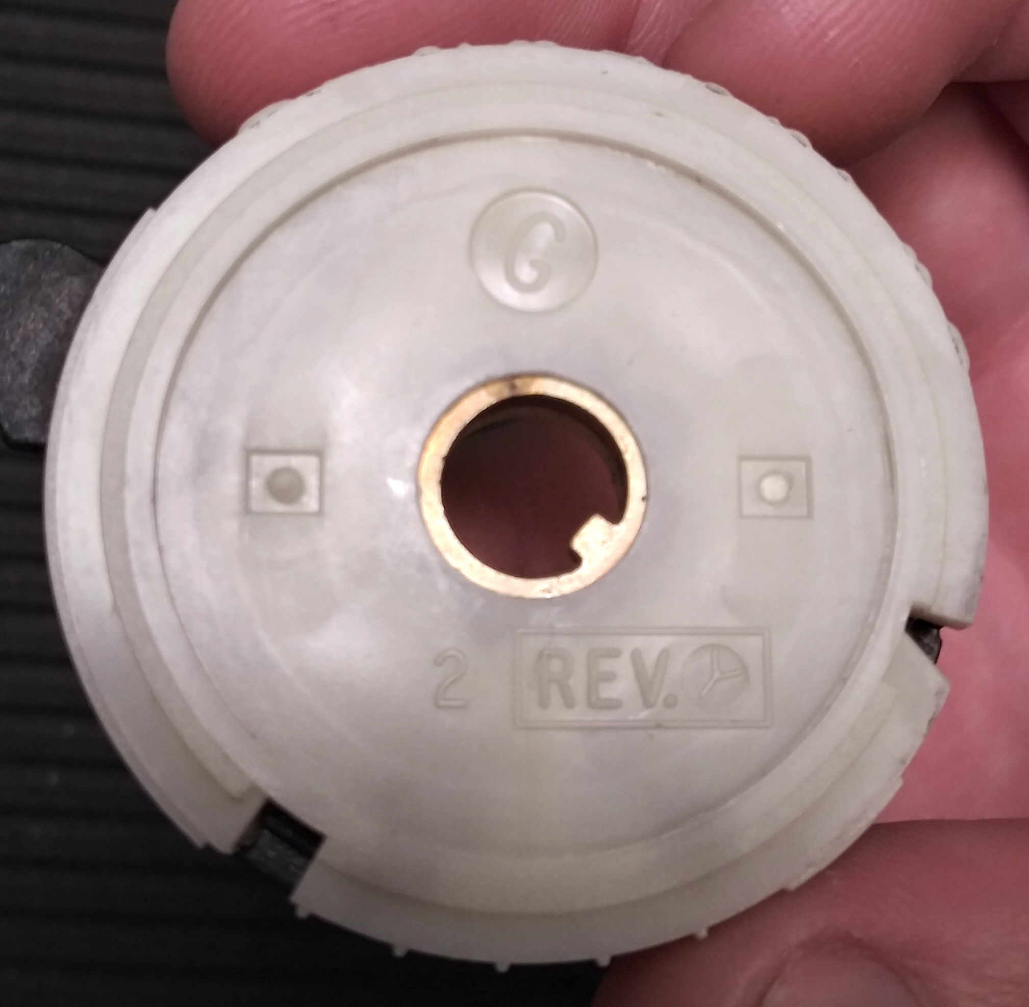
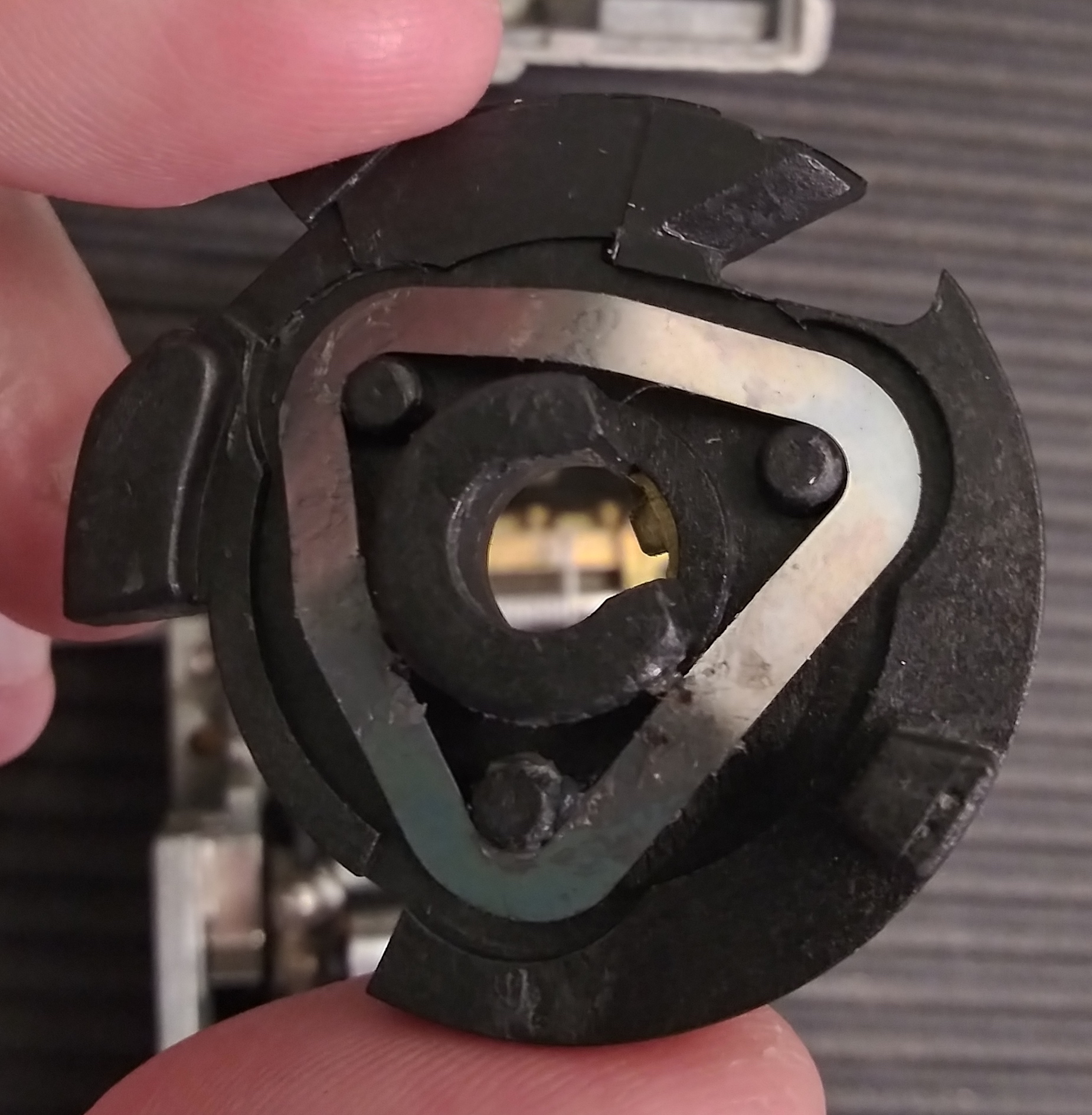
Code wheels appear to be stamped with a letter indicating their gate configurations. Around the rim of the coded white wheel you can see
the numbers that are imprinted into the foil when a key is turned and pushed, the angled cutout for the shackle release fences, and the
rectangular cutout and false gates for keybox release fences.
The black combination rings appear to have only detents for the ball bearings and cutouts allowing the shackle release fences to enter
when the correct code is dialed on the white code wheel.
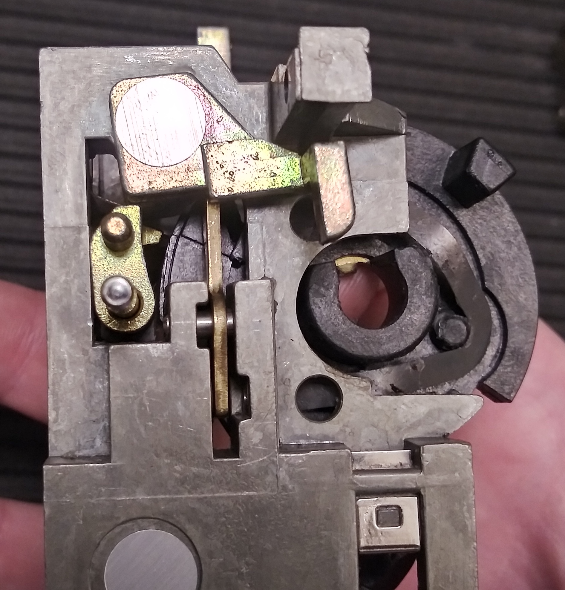
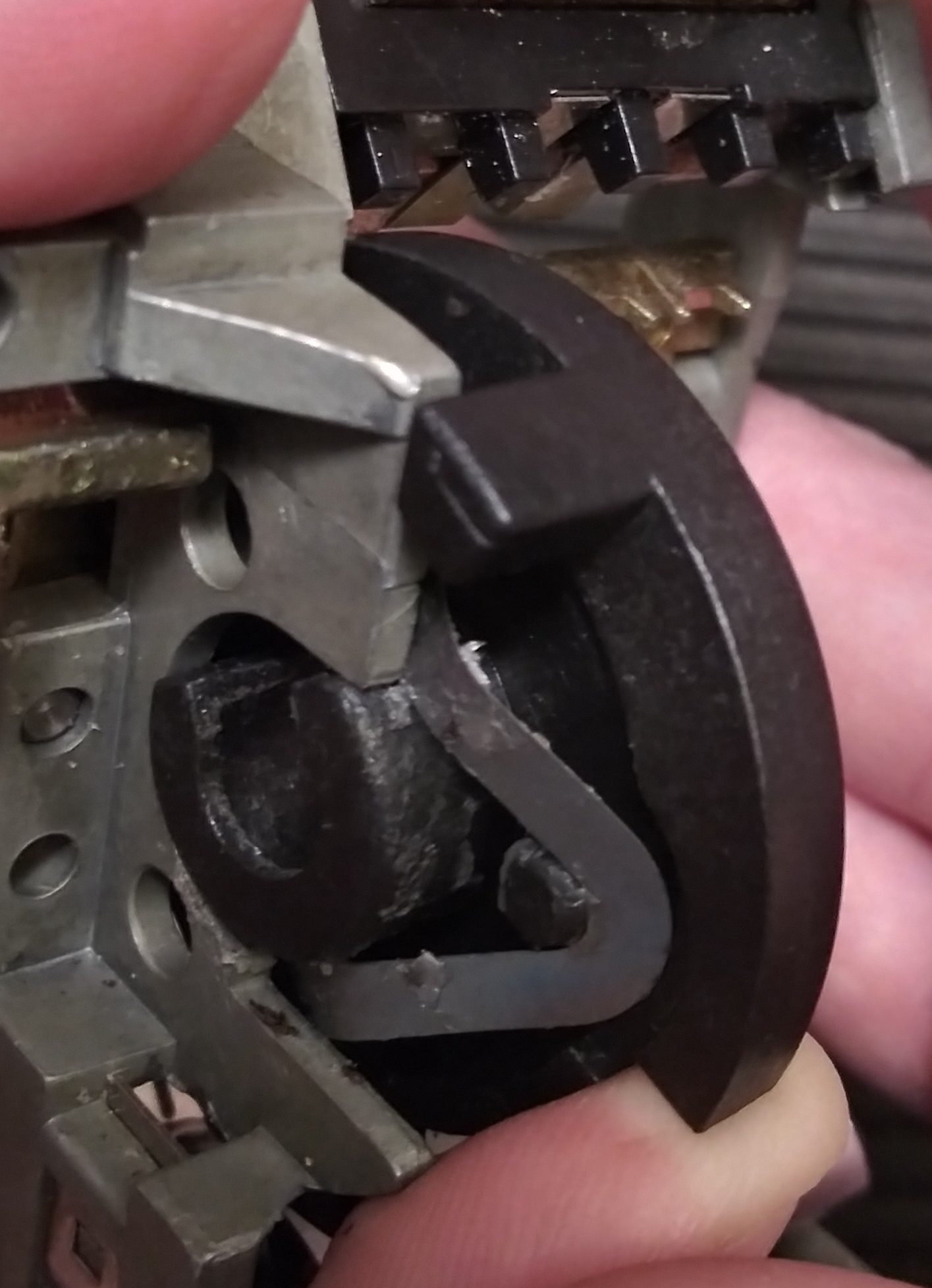
Keybox actuator blocker
The keybox actuator blocker controls whether the keybox actuator bar is allowed to descend enough for the fences to contact the
code wheels and test combinations for an open. It's shaped approximately like the uppercase letter "C" and pivots on its center
back and forth between open and closed positions. It's located nearby the keybox-retaining spring latch.
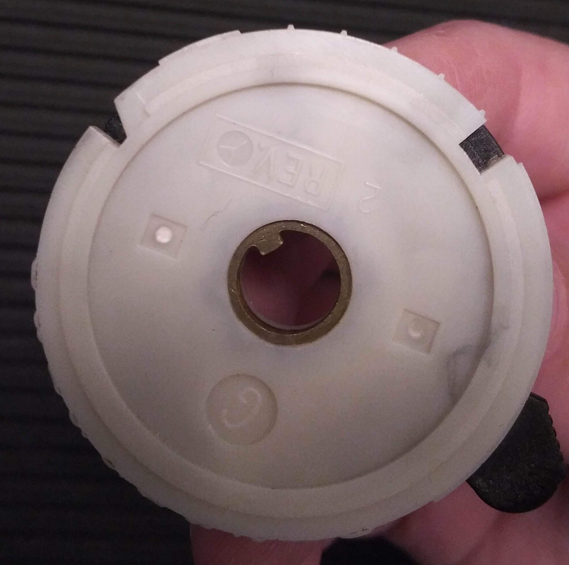
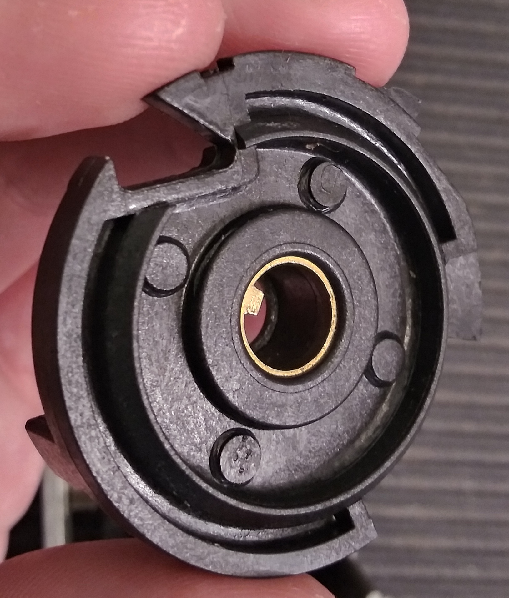
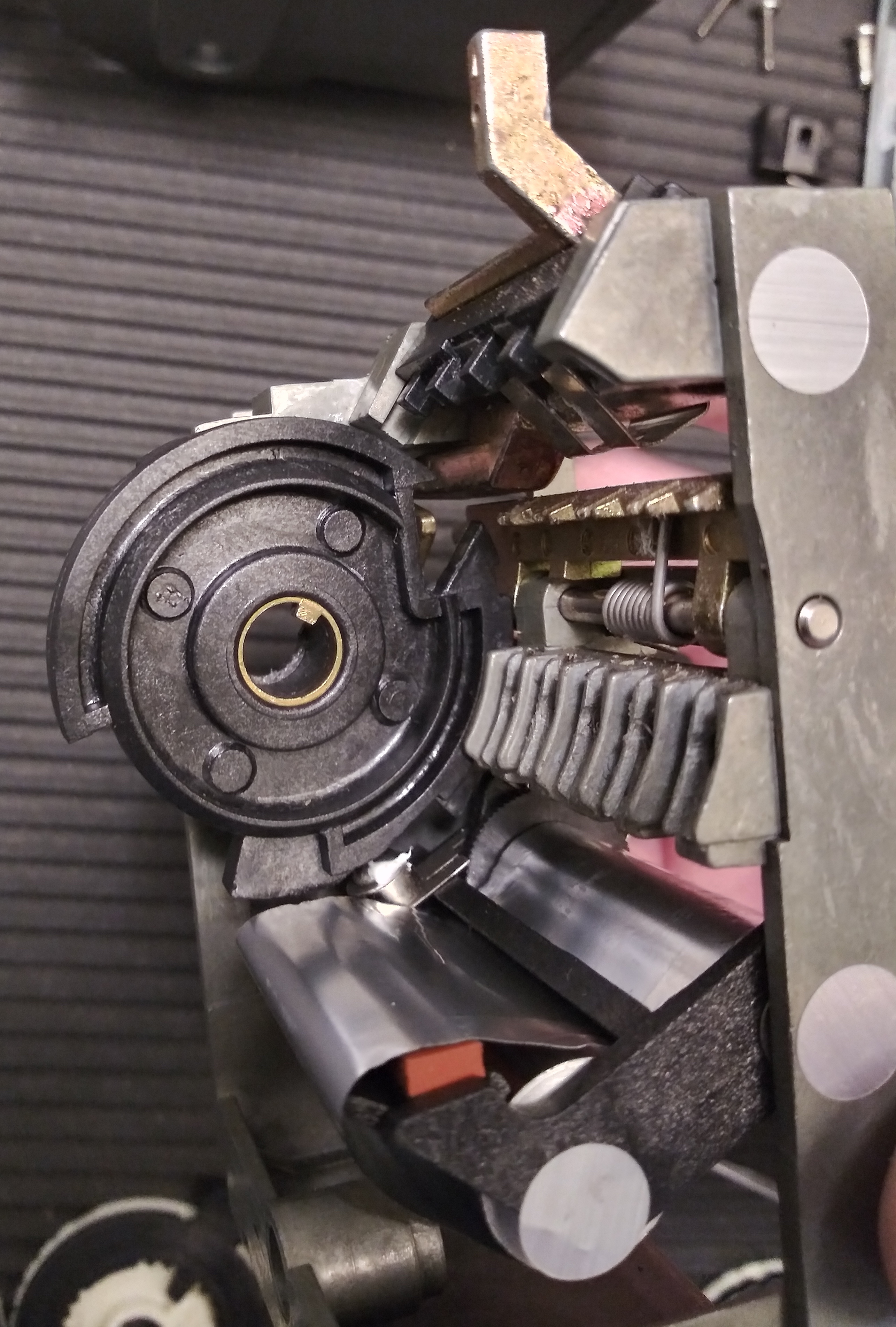
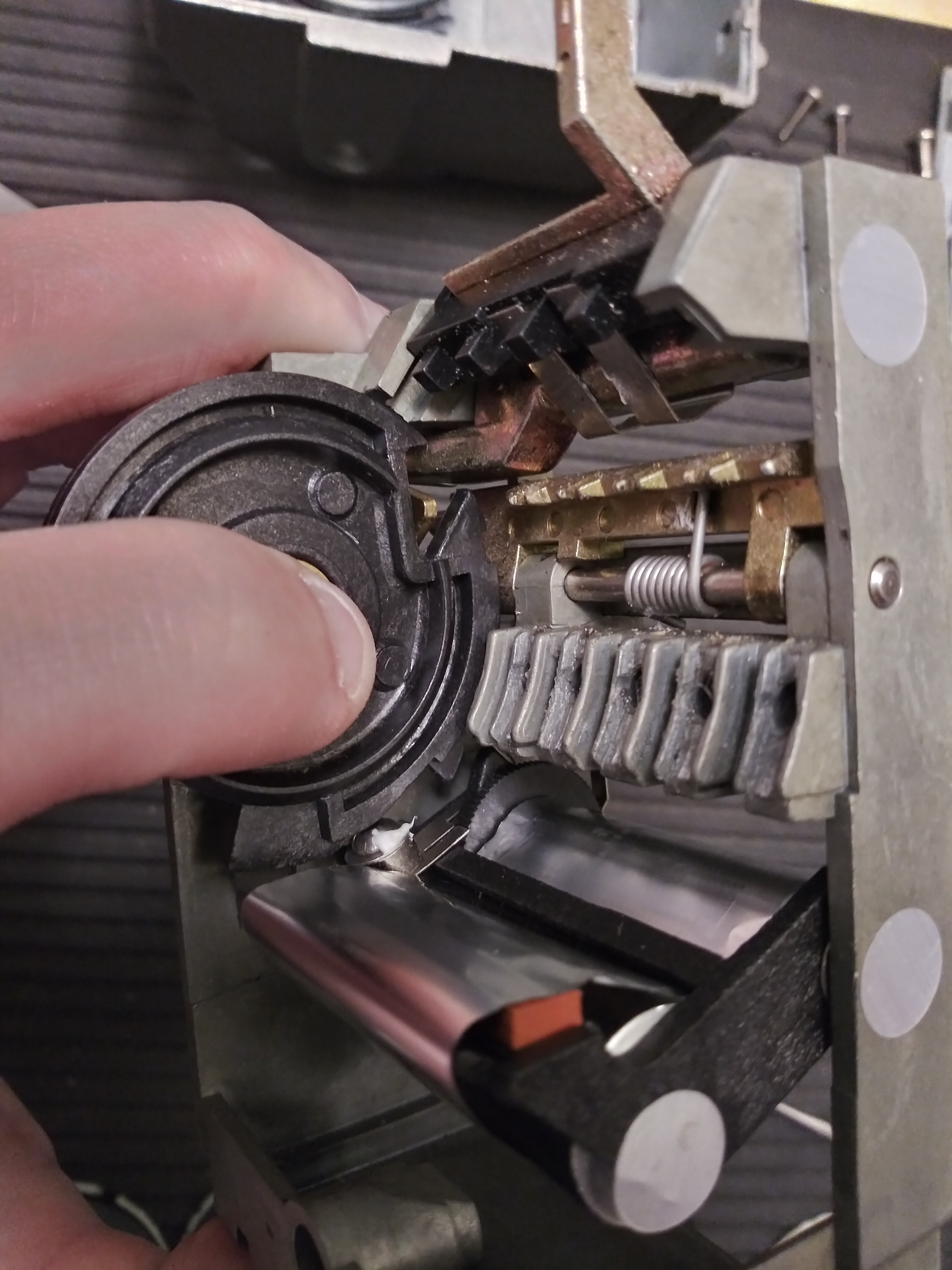
The keybox actuator blocker's behavior is controlled by the black plastic sequencing wheel that also functions as the end of
the keyway. In its rest position, the interior lug is at the top of the keyway, matching the code wheel lugs. The cutout for
the keybox actuator blocker isn't aligned with the blocker itself, holding it in the closed position. The triangle-shaped leaf
spring and corner posts hold the sequencing wheel away from the side of the inner housing. (Note the two holes in the inner
housing that can accommodate the corner posts when the sequencing wheel is rotated, as well as the plastic protrusion on the
upper right of the back side that will limit rotation.)
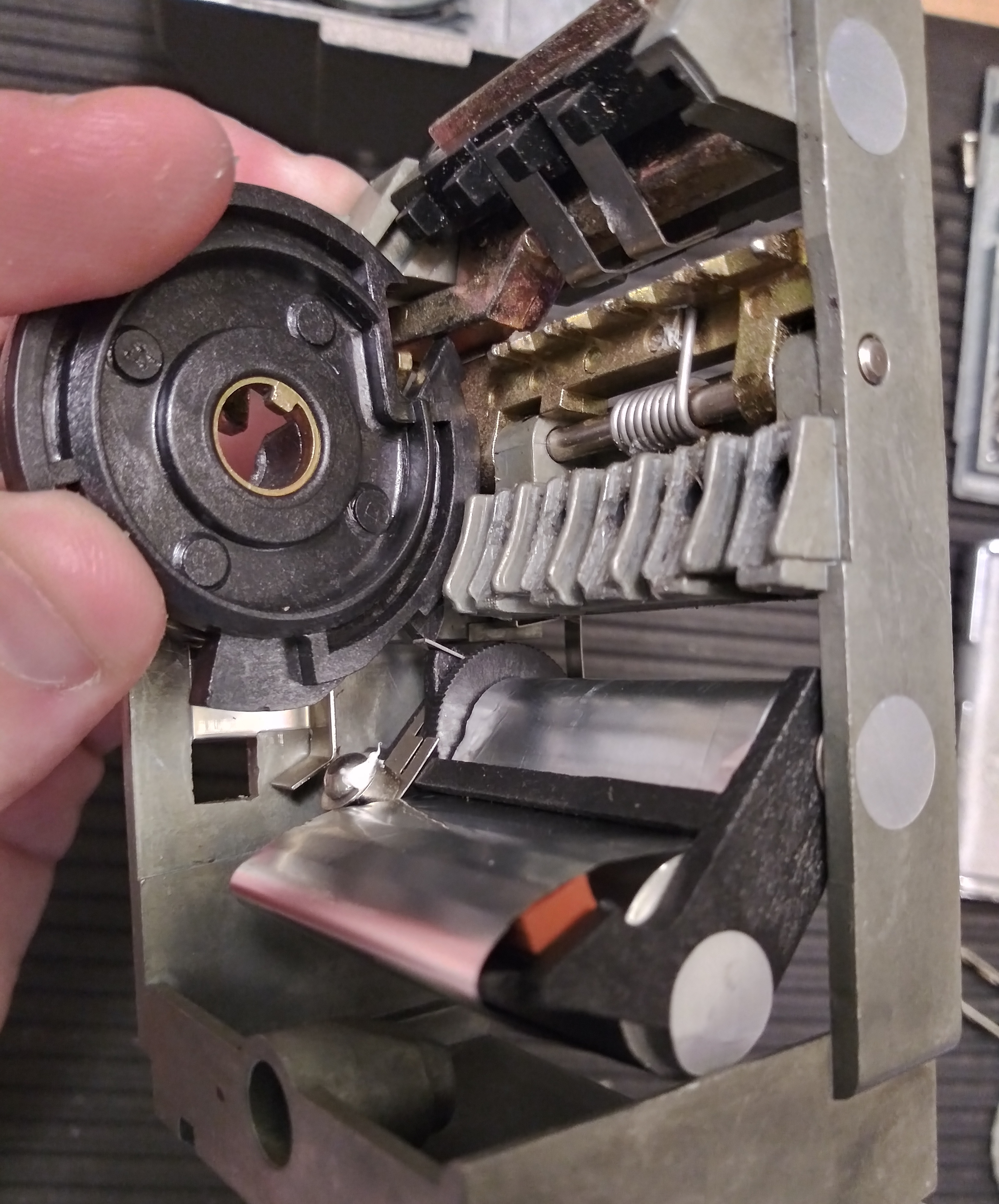
When the key rotates the sequencing wheel via the internal lug, two things happen: the foil audit trail assembly is moved downwards
against spring pressure, priming it to return and imprint on the code wheels, and the cutout for the keybox actuator blocker is moved
into alignment with the blocker. Note that the blocker is still in its vertical position and prevents opening or decoding. The plastic
protrusion on the back of the sequencing wheel caps rotation at approximately 39 degrees clockwise.
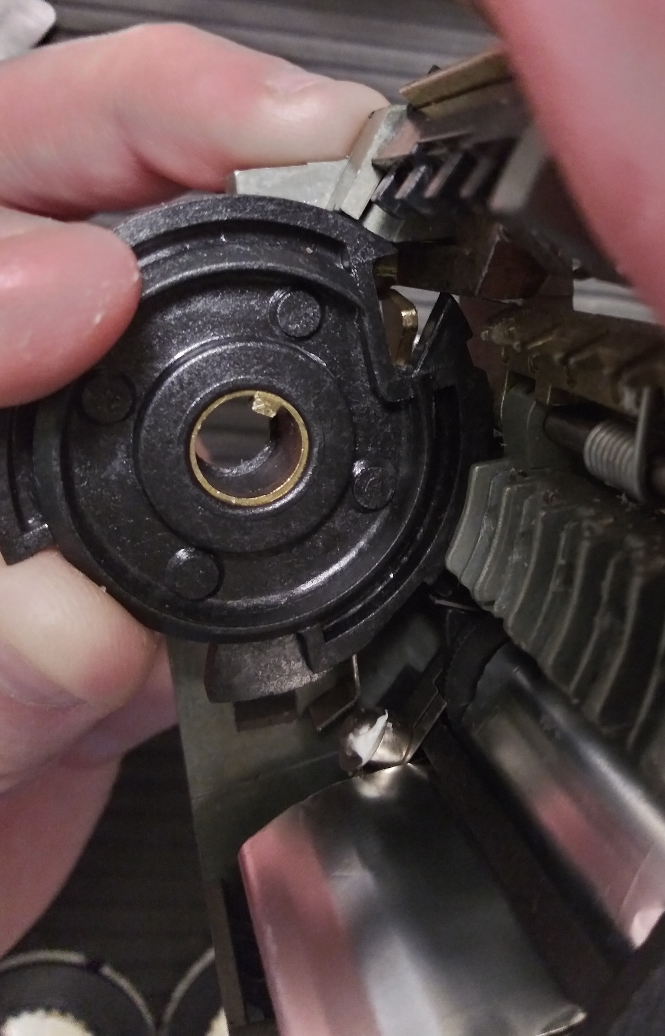
Pushing in against the fully rotated sequencing wheel releases the foil audit trail mechanism, snapping upward and imprinting against the code
wheels, and contacts the bottom of the blocker, pivoting the top inward and clearing the path for the keybox actuator mechanism.
Moving the sequencing wheel back to its rest position will slide the cutout back to the left, pivoting the top of the blocker outward
and again preventing the keybox actuator bar from descending and the fences from contacting code wheels.
Notes on code wheel ranges
Internal lugs rotate in increments of 12 degrees, as measured from the detents using a protractor. Lugs can move up to 10 increments
forward independently of the combination rings. The sequencing wheel is capped at a rotation of 39 degrees, or approximately 3¼
increments, and therefore isn't contacted by a key until around the 7th increment of rotation.
Interestingly, the actual increments for keybox opening true gates may be restricted to the range 5-10, based on the shape of the
key and the false gate configurations discovered on the code wheels. To return lugs to their neutral position and allow a key to be
withdrawn, the side of the key opposite the "bayonet" cuts must be straight. This means that the more a lug is rotated by a key,
the narrower its channel width, and a combination ring can't move the code wheel forward past the straight wall on the opposite
side of the key. Hence the restriction of the total movement of the code wheel lugs to the maximum possible using a key itself: 10!
True gates for the shackle release mechanism, while not sharing the same restrictions, may be limited to the range 0-5 due to the positions
of cutouts on the combination rings.
Also of note: cuts on the key can be made all the way to 0, a theoretical "no rotation" of the internal lug. However, to imprint properly
on the foil audit trail, code wheels move one increment greater than their cut would suggest, and our 0 cut will actually still
increment an internal lug by one position.
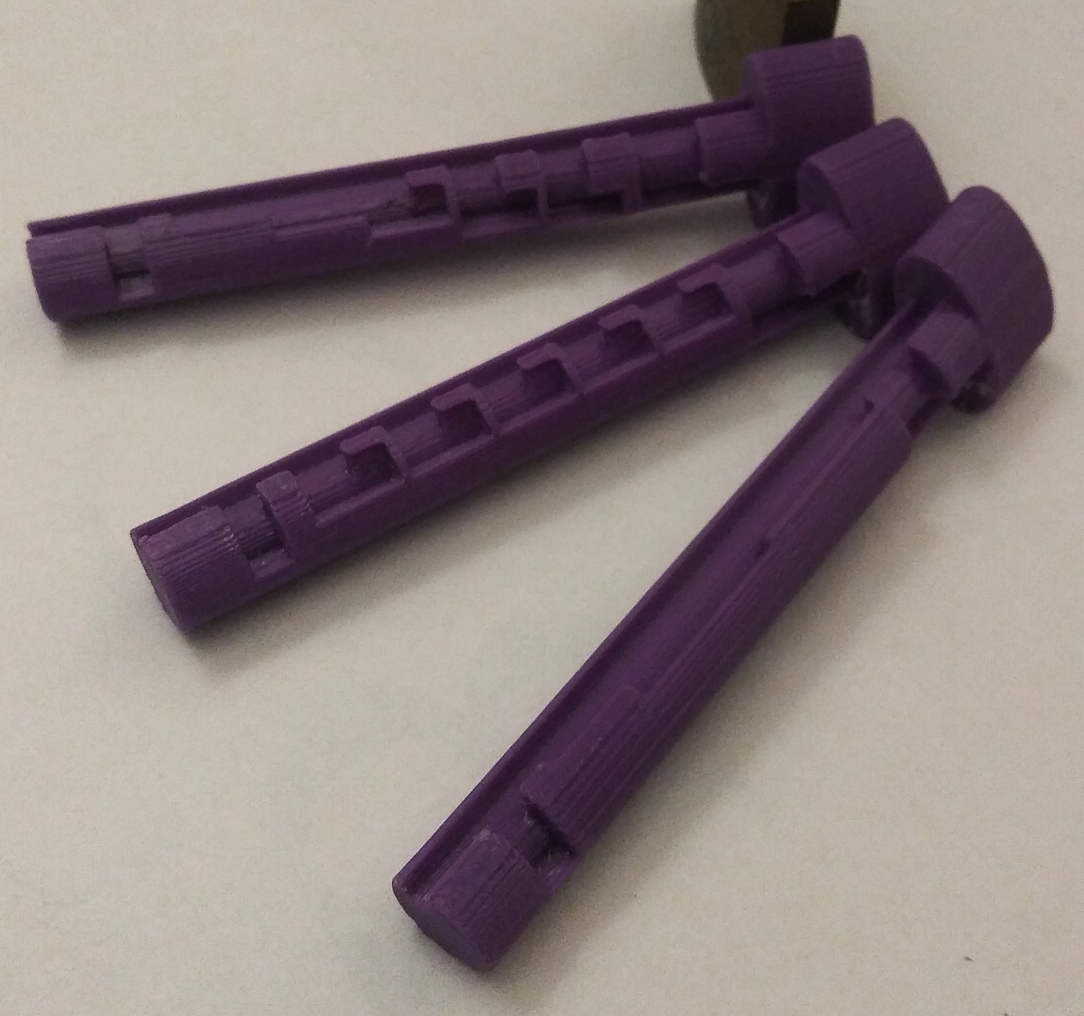
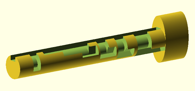
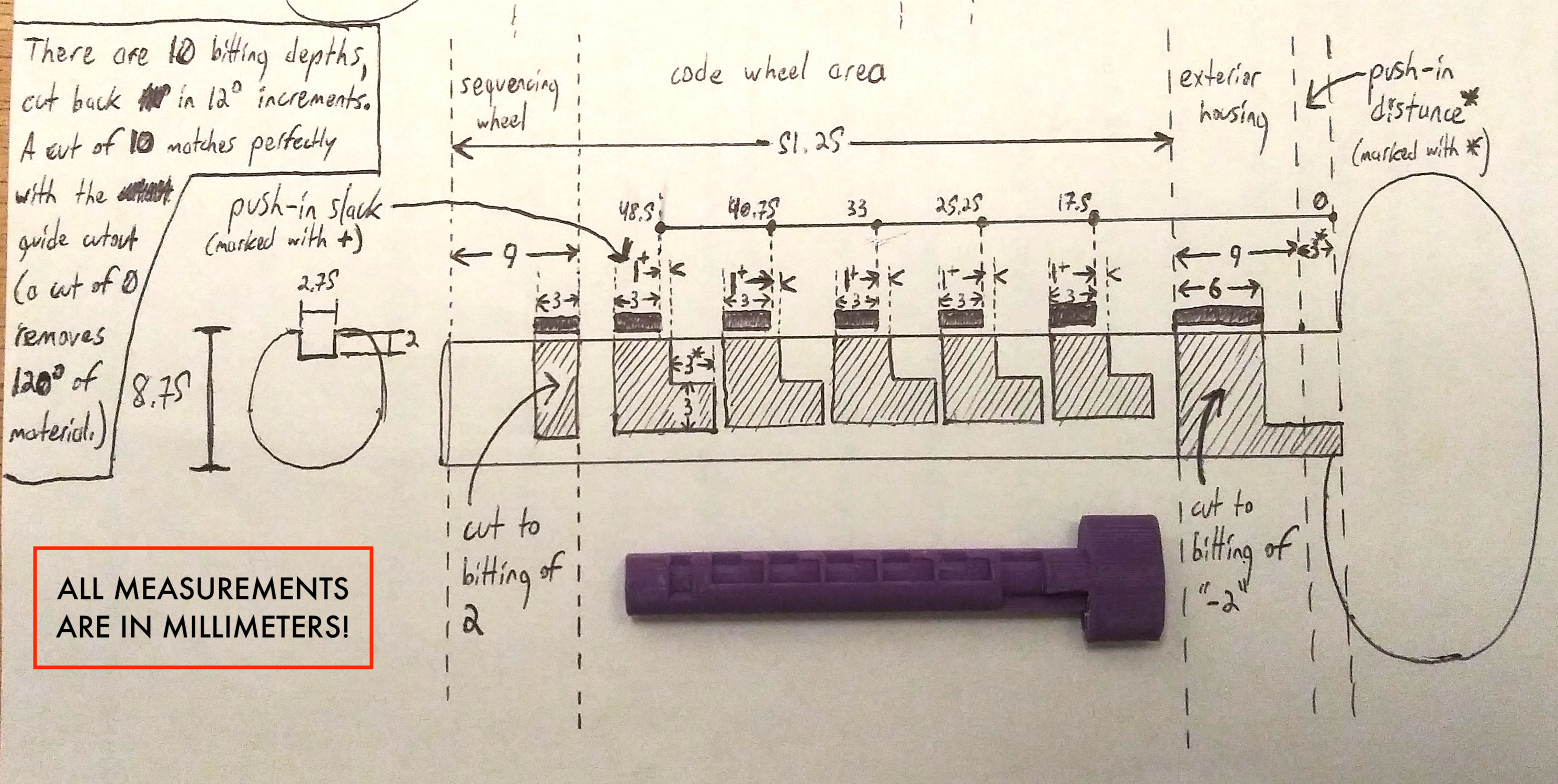
Originating 3D-printed keys
Based on measurements for the single lockbox I have, I've had success modeling and 3D-printing arbitrary keys. The bitting in the OpenSCAD file
can be changed to range from 0-10 ("no rotation" to "maximum rotation".) Keys seem difficult to fabricate conventionally so I hope this is of use to you.